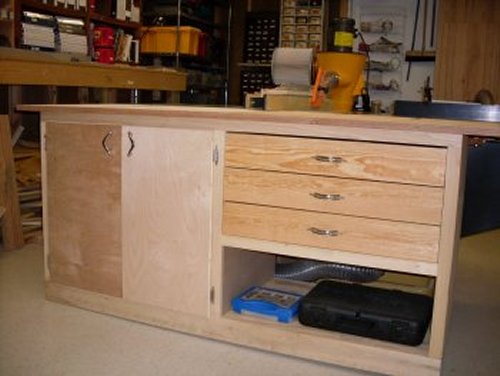
The first outfeed table on the P66 was designed for safety with sheet goods as they came off the table saw, a downdraft sanding station and storage space. |
|
The downdraft sanding table had been a noble idea but immediately after completion I bought the MFT3 table and Festool vacs and sanders, etc. The downdraft table was simply never used. |
 |
The ductwork underneath the table top took up an immense amount of useful space. |
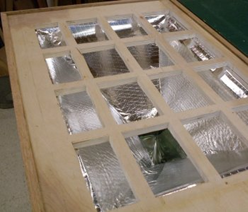 |
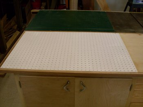
During the extreme kaizen overhaul transition to hand tools, the useless downdraft station was removed. At this time plans began for a new top. |
 |
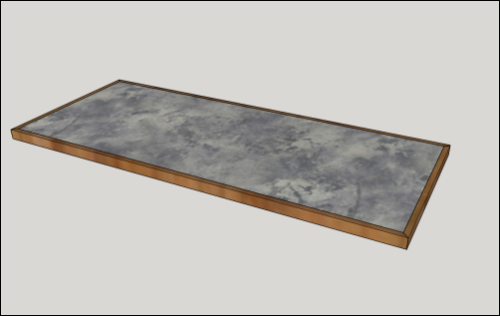
Thus we began to talk out the new top...we settled on two thicknesses of plywood with a Formica laminate top. It will have oak side bands. |
 |
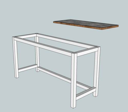
...and then the design became a whole new workstation... with a very open structure. The frame will be 2 x 2 southern pine. Construction style will be based on the assembly table. |
 |
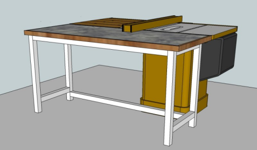
The rear strether will be low enough to accommodate the 5 inch dust collection from the rear of the Powermatic. |
 |
The outfeed table area has been used more and more as an assembly area and general use area. So we wanted to maximize clamping potential. Clamp grabbing overhangs will exist on the front and on the south end.
|
 |
A clamp rack will be installed on the south end of the frame. |
|
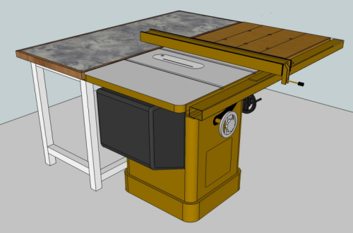
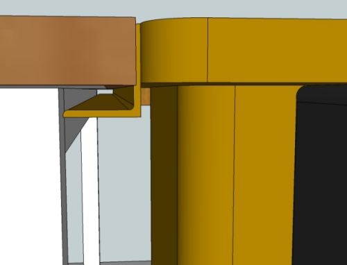
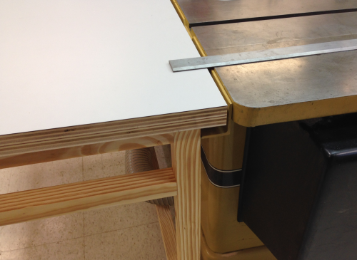
The rear of the frame will abut the L bracket on the rear of the P66. The top of the outfeed table will abut the P66 cast iron table and will be coplanar with the table.
|
 |
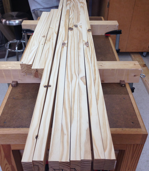
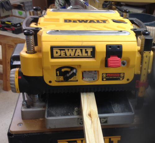
Southern pine 2 x 10s were purchased, ripped into smaller widths and then seasoned in the attic. After a couple of months they were surfaced and edged at the jointer. |
|
The blanks were then surfaced at the planer down to 1 inch and ripped to 1 7/8 inches...the blanks were matched up and were now ready for gluing. |
 |
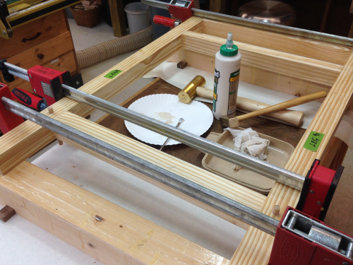
The blank were glued up at the assembly table in pairs and put into the stack. |
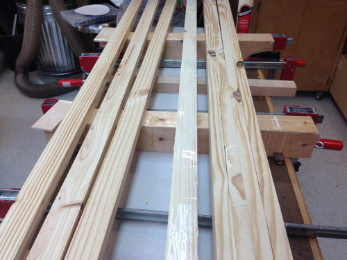 |
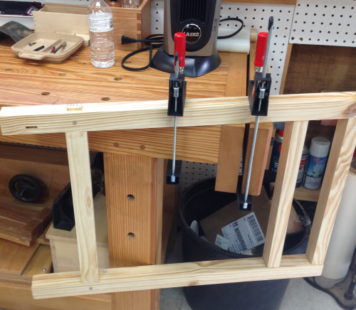
Cauls were used to keep the boards horizontally coplanar. |
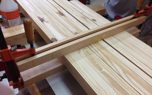 |
Many cauls and clamps were used for good squeeze out. |
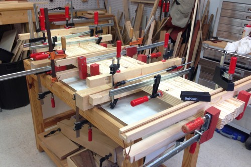 |
Next day the glue up was released...a total of five pairs of cauls and two dozen clamps had been used...further proof of the adage "You can never have too many clamps". |
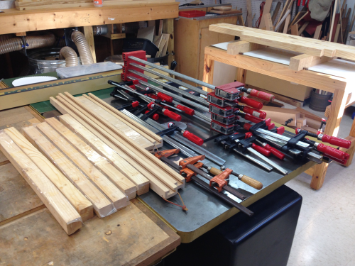 |
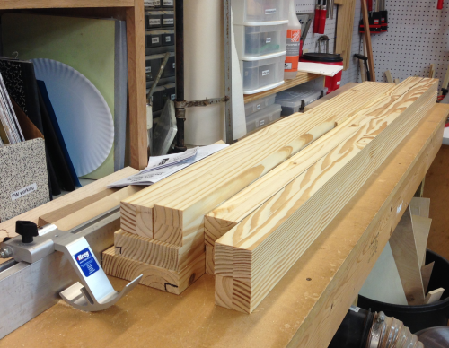
The blanks... |
 |
...separated. |
 |
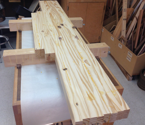
After cleaning glue off with chisels...one glue squeeze-out face was run across the jointer and then the opposite face was planed down to 1 3/4 inches. |
 |
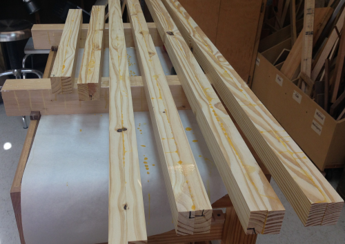
The blanks were put aside to allow for wood to detension...
|
 |
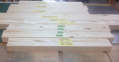
Then all the pieces were planed to the final dimensions and selected and marked for individual pieces. |
 |
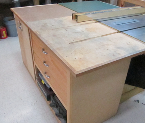
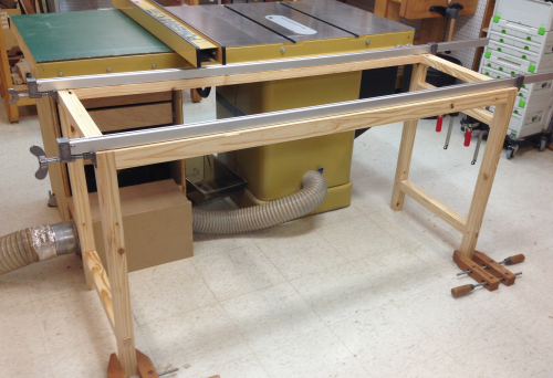
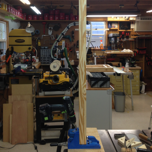
Preparing for assembly of carcase...killed the old outfeed table. |
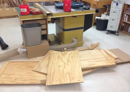 |
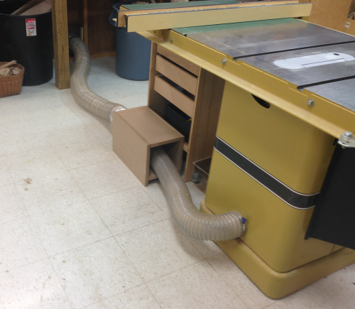
Good view of backside of P66 and the dust collection system. |
 |
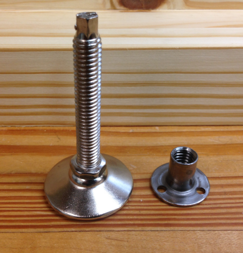
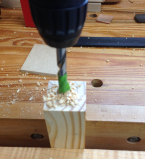
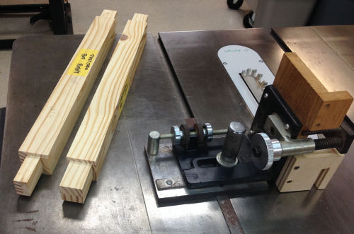
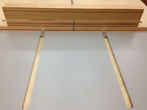
The legs...the leveling glide fits into a base that will screw onto the bottom of the leg.
The hole in the leg will need to be 3/8 inch to accept the bolt. |
 |
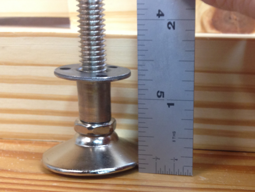
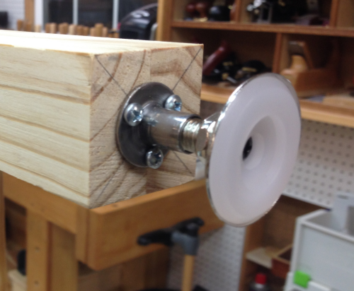
The minimum height of the base and swivel leg is ~1 3/8 inches. |
 |
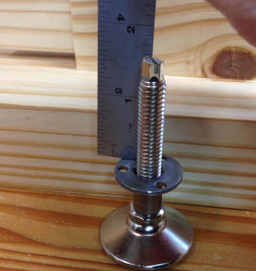
The threaded bolt above the base at minimal runout of threading is ~ 1 5/8 inches... |
 |
A 3/8 inch hole was drilled in the bottom of each leg to accept the threaded portion of the leveling assembly. |
 |
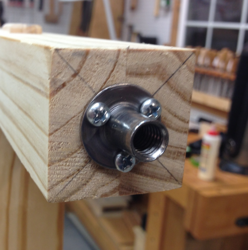
The base installed... |
 |
...and the leveling pad screwed in. |
 |
The 31 inch long leg blanks are 1 3/4 x 1 3/4 inches square. The mortise is through...3/4 wide x 1 1/4 inch tall...so I used a 3/8 inch mortise bit and ran two passes. |
 |
Mortised an inch deep from one side and then the other to minimize tear out... |
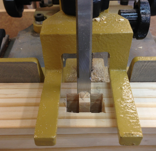 |
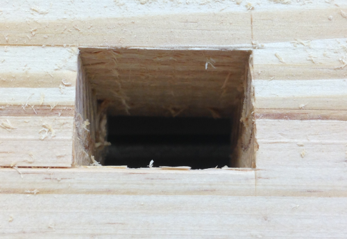
Through mortise just needed a little clean up with chisels. |
 |
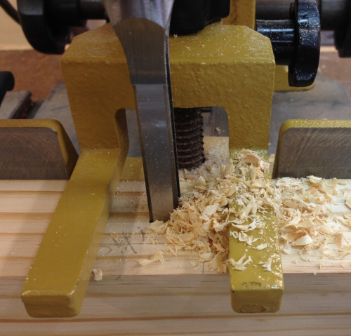
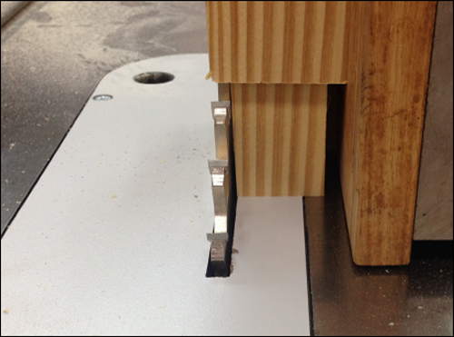
The lower stretcher will join the legs with a 1 7/8 through tenon. The tenons will be cut at the Powermatic using a tenon jig and an Infinity 1/4 kerf blade. |
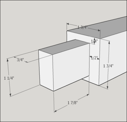 |
| Using the ¼ kerf blade I set to remove just the outer ¼ inch slice at a height of 1 7/8 (to set the length of the tenon). |
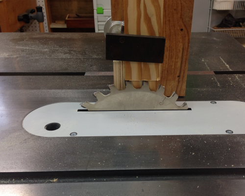 |
I did this on all four sides…A second pass on two sides created the tenon width. |
 |
The crash test dummy looked pretty good. |
 |
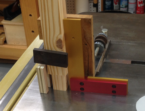
| During the actual tenon process the height of the stretcher and the fit of the jig holder caused some minor issues as to how clean the shoulders were. | 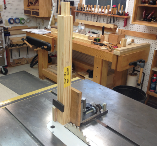 |
Carefully squaring the work piece helping reduce the issue but it was not eradicated...design alteration on the jig will be required... |
 |
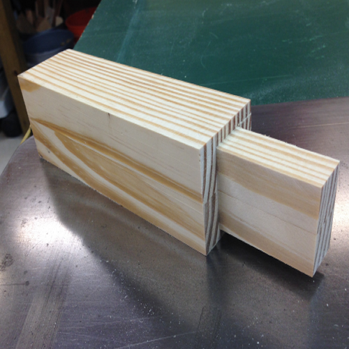
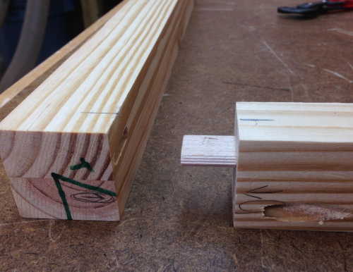
The tenon on the right has had a 1/4 inch taken off the four sides...the one on the left has had the 1/2 removed on two sides.
|
 |
All of the tenons and mortised have been cut...chisel clean up and fit tweaking is required... |
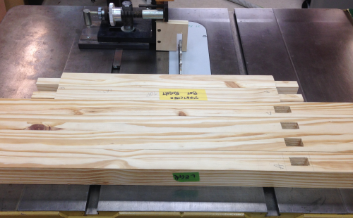 |
Dry fit... |
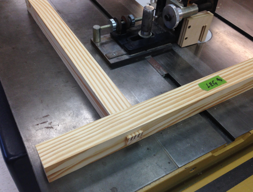 |
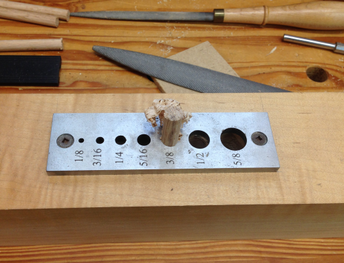
The mortise and tenon joints will be locked in with drawbore pins...3/8 inch oak dowel stock was tapped through the LN dowel plate to clean them up. |
 |
Then 3/8 inch holes were drilled all the way through the legs centered over the mortise hole. A spacer tenon was pounded into the mortise to prevent spelching. |
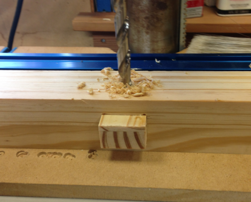 |
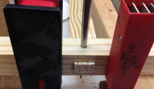
The tenons were put back into the mortises and the joint was clamped tight...the 3/8 inch bit was used to define the hole location in the tenon. It was tapped with a hammer... |
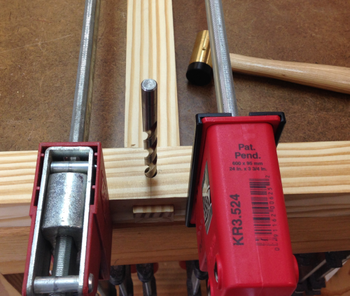 |
...leaving a clear mark... |
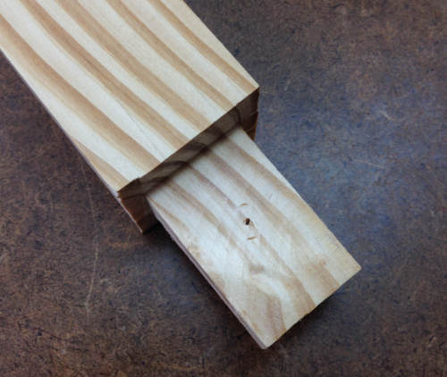 |
...and the hole was then drilled about 1/32 inch closer to the shoulder of the tenon. |
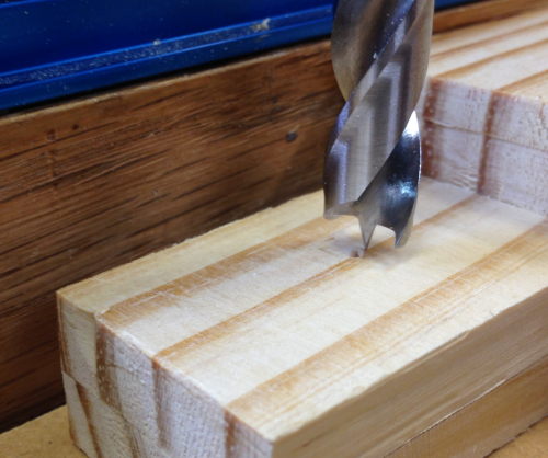 |
The top stretchers, the clamp rack, and the legs all received Domino mortise and tenon joinery (6 mm x 30 mm). The boring was performed using the Domino production jig. |
 |
The mortise in the stretcher was bored in tight fit size...in the legs it was bored in medium fit. A Kreg pocket screw hole was added to the top of the stretcher. |
 |
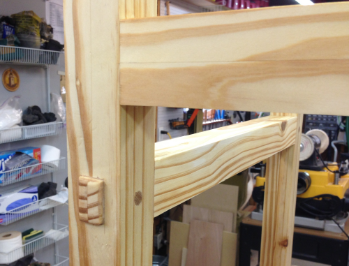
During glue up, clamps were used to pull the joints in tight...the top stretcher was screwed through the Kreg pocket joint...the mortise and tenon was brought super tight with a LN drawbore pin. |
 |
The oak dowel was pounded down through the joint. |
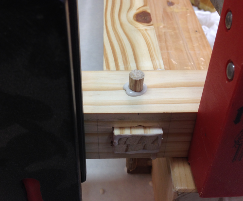 |
Section was glued, screwed, drawbore pinned and clamped for drying. |
 |
Then the two ends were dry fitted with the front and rear stretchers...all joints had their final plan conceived for location of Domino tenon, Kreg pocket screws, etc. |
 |
Lower back examined... |
 |
The Domino mortises were bored with the odd shape of the end frame handled just fine in the Domino production jig... |
 |
...an alternative fit... |
 |
...and the one boring that did not work in jig was done at the workbench...it was nice to have the long Festool power/vac line. |
 |
The Kreg pocket holes were done awkwardly with the long stretcher board in the jig. |
 |
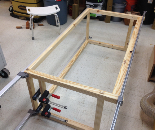
The weather turned warm enough for my beloved to assist me during the glue up. Cindy and I got all the joints happy and clamped up the carcase...used the 72 inch long Dubuque Universal bar lamps...they were perfect for this job. |
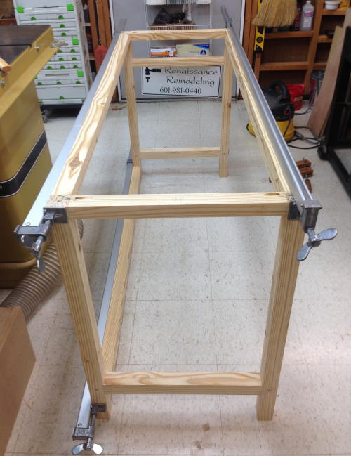 |
After glue up...I put on a coat of tung oil. |
 |
Then I laid the slab onto the frame to make sure that I could easily level the table and still have the table top be just below the surface of the P66 cast iron table. I had a few issues but resolved them...I had to adjust the P66 a bit. |
 |
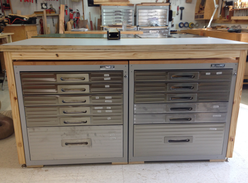
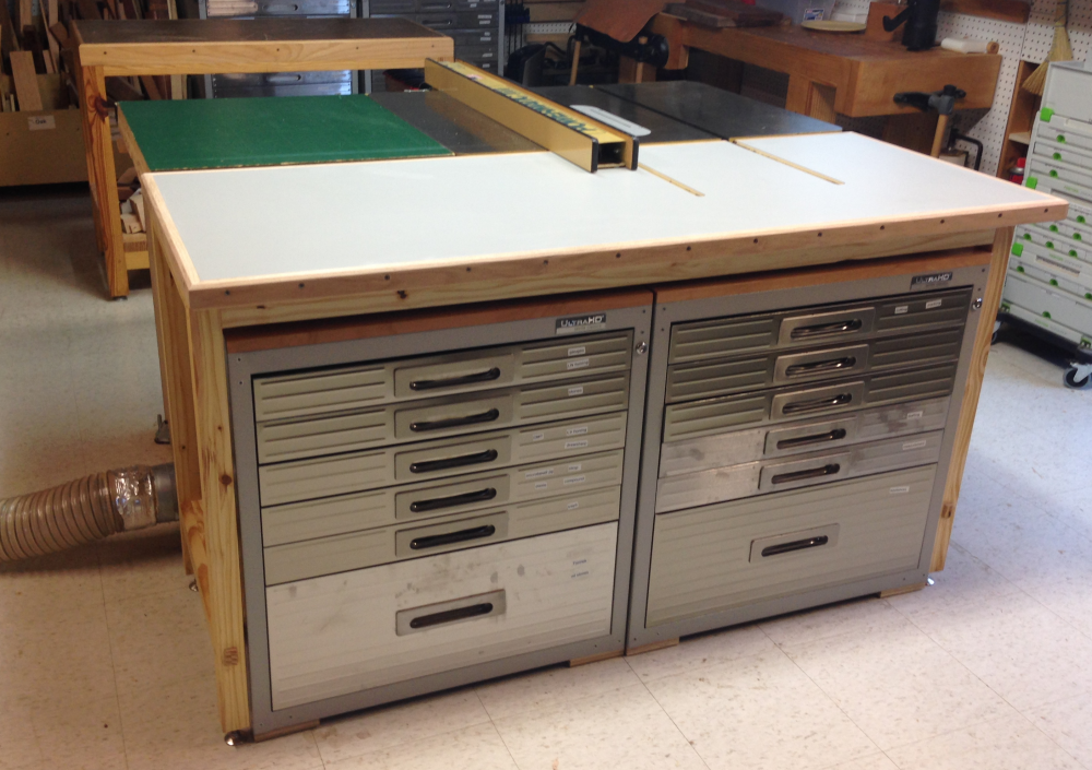
Under the table will be two side by side 6 drawer cabinets...Seville Classics HD. Normally they ride on large 5" caster wheels. I will use them without casters so that they will fit under the outfeed table.
|
 |
However, without wheels the unit would be hard to move and would mar the floor. So I created a pad that would allow the caster wheel bolts to be used to secure a plywood pad with a furniture glide on it. |
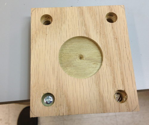 |
The bolts had a recessed 1/2 hole to allow the bolt to be countersunk. The through hole was 3/8...a 1 3/4 inch shallow hole made with a Forstner bit allowed the cushion with an adhesive to sit in it nice and tight. |
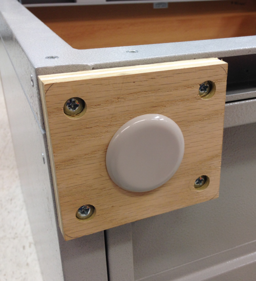 |
A quick fit to make sure all went well...the cabinet slid easily and fit with a bit of extra space. |
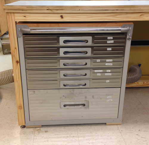 |
Both cabinets...test fit. |
 |
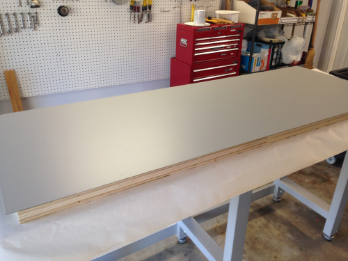
The top will be a two layer thick slab made from 3/4 inch cabinet grade oak plywood. The sheet goods were unloaded and cut with the track saw at the BenchMark table in the garage before migramtion to the shop. |
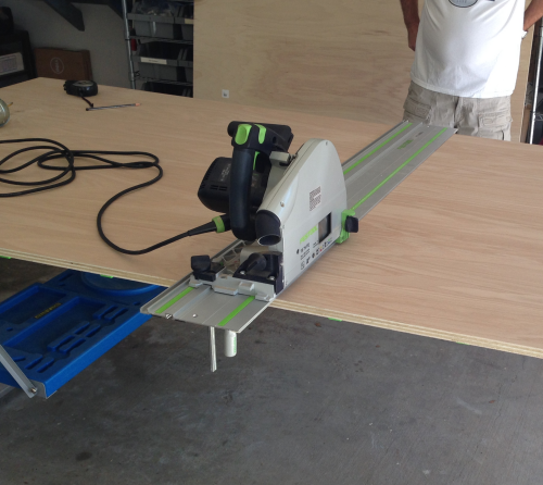 |
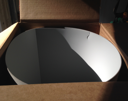
The plywood top will be covered in a 1/16 laminate (dove grey)...ordered from the orange BORG...it arrived with a small crack but it will be at an end that we do not need. |
 |
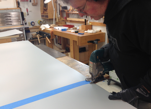
Cindy, Max and I ripped the laminate on the P66...the ends were crosscut with the Bosch jig. All edges were cut 3/8 inch oversized. |
 |
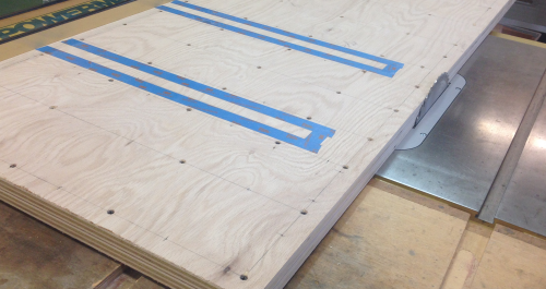
Before gluing the plywood pieces, careful attention was made to the locations of the mitre grooves for the outfeed table. Screws needed to be carefully spaced around the dado grooves that will be routed later. The area was clearly marked with blue painter's tape so that it would be easy to identify. Screw locations were marked with birdcage awl and counter bored for the heads of the 1 1/4 inch drywall screws. |
 |
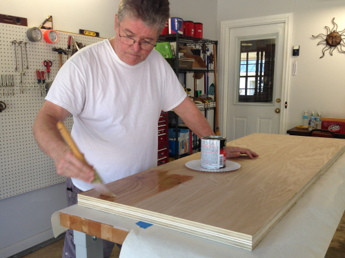
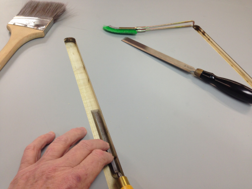
The downside of the upper ply was well coated with glue...brushed on. |
 |
The sides of the plys that will face the P66 were made co-planar with the ends as co-planar as possible. Clamps held the plys in place...some weight was put in the area between the grooves...the screwing phase started there and moved outward. |
 |
After several hours the slab was removed from the clamps...the most non-planar long edge was ripped at the P66 and then reversed and ripped on the other long ege. |
 |
The ends were squared and made co-planar at the MFT3 table. |
 |
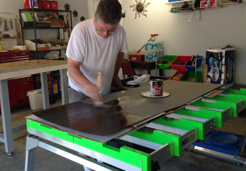
Cindy and I laminated the slab in the garage...the wood slab was laid on a workbench and the contact cement was brushed on...took about 7 minutes. |
 |
The laminate backside was coated at the Benchmark work bench. |
 |
We waited 40 minutes for the to-be-mated surfaces to dry...then we laid out dowels on the wood slab...these acted as spacers to keep the surfaces from touching. |
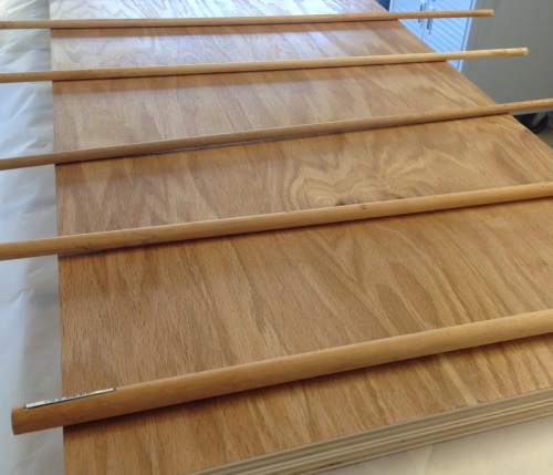 |
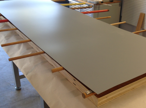
Then Cindy and laid the laminate on top of the dowels and centered the laminate so that there was an overhange on all sides. |
 |
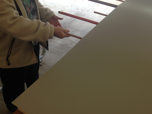
We started at one end and on cue, Cindy pulled the dowels out one by one,,, |
 |
...as I rolled out any air pockets... |
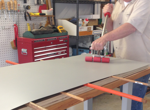 |
After all dowels were out the rolling process continued... |
 |
The laminate is down...with appropriate overhangs on all sides. |
 |
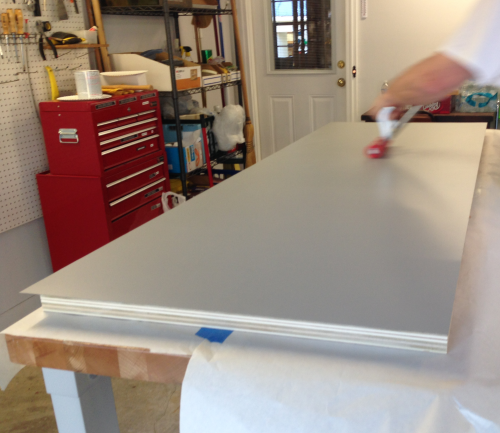
Trimming the laminate flush to the plywood...using a straight flush bit with a bearing in the PC trim router. Greased the bearing with Crisco...greatly reduced the glue build up. |
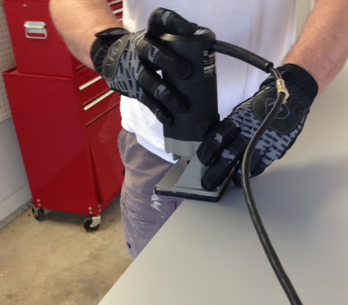 |
The finished edge trim on the laminate. This is now a 1 9/16 inch slab. |
 |
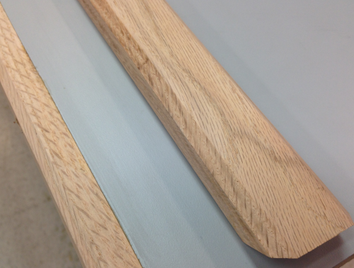
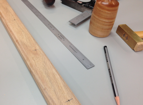
Runs of 3/4 inch oak were milled to be the banding. Chamfered on the top and bottom. |
 |
After being marked and mitered on the ends, the banding was marked out for a screw every five inches.
|
 |
Counterbored, an oak piece was glued up... |
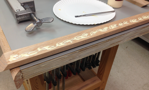 |
...then clamped... |
 |
...and then screwed ...#8 x 1 3/4 inches square drives. |
 |
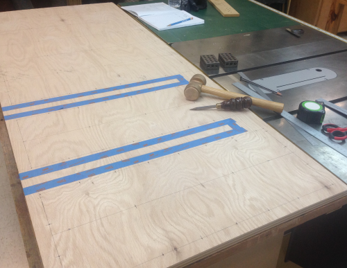
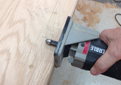
On the backside it was important to make sure that no screws were in the path of the dadoes that will be routed into the outfeed table surface. The yellow tape marks the future location of the grooves. |
 |
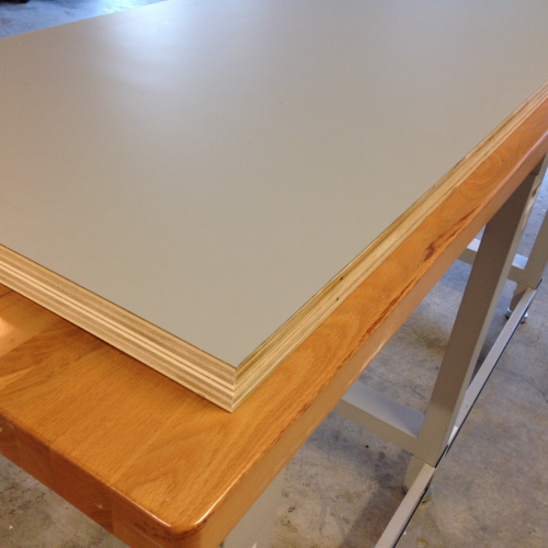
The oak banding was milled to 1 3/4 inches wide...I wanted the top edge of the oak to sit slightly proud of the top surface...I worked the top edge with planes and sanders to make the surface smooth and reasonably coplanar with the top. |
 |
On the bottom side of the edge banding there was was about 3/16 inch of oak proud of the bottom surface of the slab. I removed this lip with a router and then a sander. |
 |
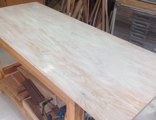
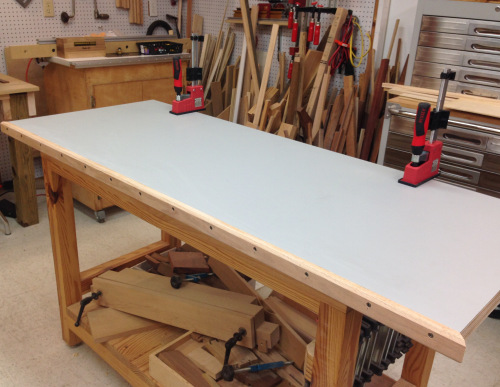
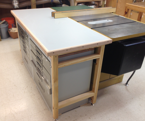
Banding done...outfeed table in service... |
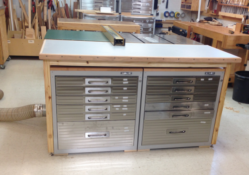 |
...will use it for a while and then finalize groove placement and secure tabletop. |
 |
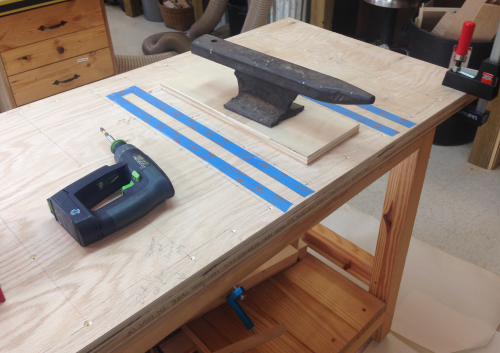
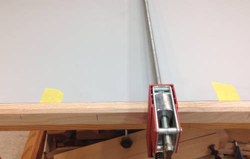
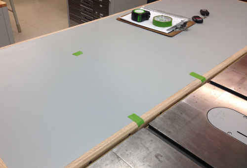
I put a few screws up through the top stretchers into the slab to hold it in place. The green tape shows where the slots are intended to go so as to miss screws...the far tape shows where to end the slots. |
 |
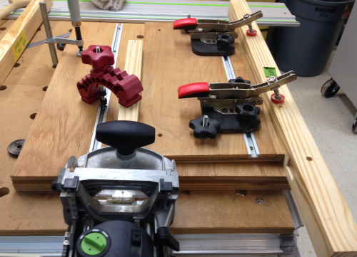
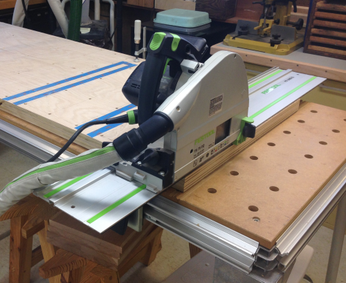
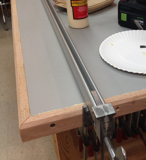
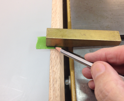
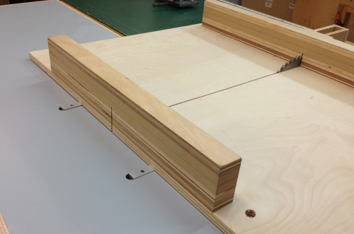
Using a brass 3/4 bar I extended the mitre slots from the P66 to the table. |
 |
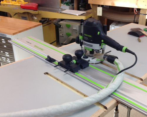
I extended those lines, found the center, squared a Festool rail and routed the two slots. The slots were tight for the single bars of the mitre gauge. The lower t-bar of the Incra gauge would not fit unless the slot is altered. |
 |
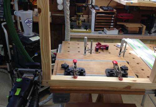
The most critical test was the placement of the slots to accept a double bar jig...like the crosscut jig. They fit, though too tightly. |
 |
Far reach of the jig was acceptable. |
 |
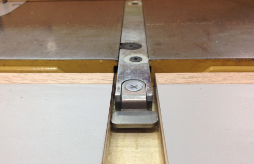
Some tweaking to be done...I gave the right slot just a skosh more width...about 1/16 inch wider...and the left one about 1/8 inch wider...used paring chisels to clean up the bottom of the slot. |
 |
The greater width of the left slot will allow the Incra mitre gauge bar to run through into the outfeed table with the lower t-bar fixture in place. |
 |
 |
|