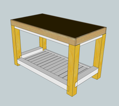
Assembly Table Project While planning the build of the new workbench, I decided to first build an assembly table. I will use the same kinds of wood and joints that will be included in the workbench. This will allow me to practice some new skills with new hand tools. In particular, just like the workbench, the legs and stretchers will connected by mortise and through tenon joints that will be wedged and have drawbore pins. These practice joints will will be good warm-ups for the big build. I decided on a torsion box top for stability without excessive
weight. This will help ensure that the surface stays fairly level. Here is the sketchup with the first ideas.
|
|
|
The torsion box top will be made of 1/2 MDF with a 3/16 tempered hardboard top. The top sheet will be sacrificial and replaceable. The outside of the torsion box will be trimmed in oak for protection. All legs and lower stretchers will be 2.5 inch square in yellow pine. Upper stretchers and the shelf will be 1.25 x 2.5 inch yellow pine.
|
|
The wood for this project was purchased when the materials for the big workbench were secured. The 2 x12s were reduced in length and stored in the attic of the shop. |
 |
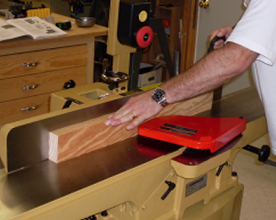
James and I started the project on a rainy day. After selecting 3 units of the 6 foot long 2 x 12s from the attic we milled these pieces down to 1 1/4 inch by 2 1/2 inch. The milling process of rip, joint a face, plane an edge, and rip again was phase one. |
 |
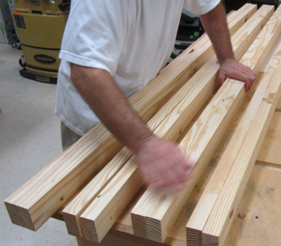
Phase one gave us 8 boards that were then paired up for gluing. |
 |
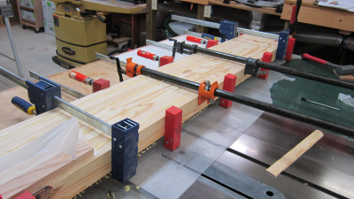
The four pairs were glued and clamped in one session. |
 |
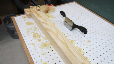
After removing the clamps, the four sections had to be milled again. First the glue joint and uneven edges were knocked down with the Stanly #80 scraper. |
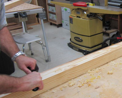 |
A few minutes of serious hand work cleaned up the four units and they were ready for jointing and planing a second time. |
|
The second milling provided
very nice slabs that are 2 1/2 x 2 1/2. They were examined for faults
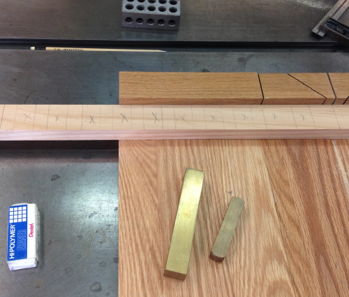
and seams and the legs and lower stretchers were marked out. |
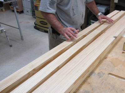 |
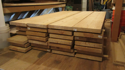
Some chop saw work dimensioned to length. Here are the 2.5 inch square blanks for the four legs, two long lower stretchers and the two side stretchers. |
 |
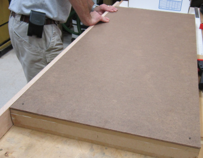
Attention was then turned to the creation of the torsion box assembly. The runners, caps, dividers, top and bottom were all made from 1/2 MDF. Assembly used glue and 7/8 staples from the Porter Cable air-powered crown stapler. |
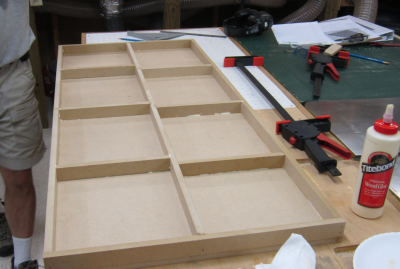 |
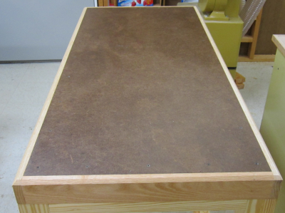
Here is the finished top with the tempered hard board screwed on. The oak edge boards are being dry fitted.
|
|
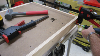
Oak boards were attached with
screws and glue. |
 |
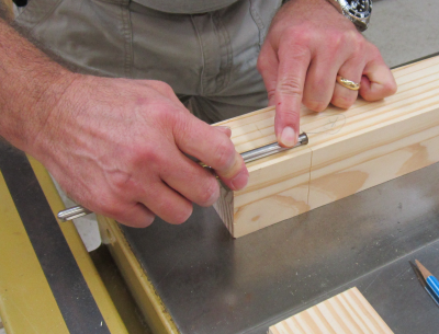
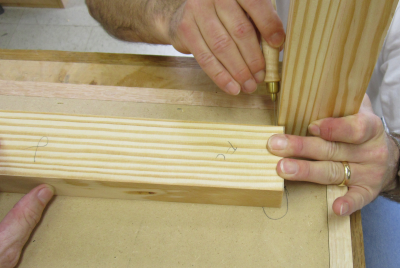
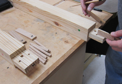
While the torsion box set up, we marked up the ends of one of the stretchers so that we could try out our tenon size. All four faces were laid out with the TiteMark marking gauge for precision.
|
 |
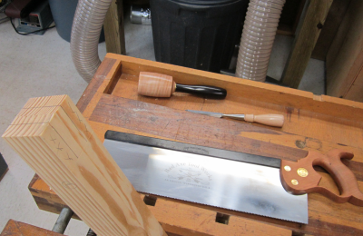
After paring a starting wedge
with a chisel, the tenon cuts were made with a Bad Axe 16 inch saw. |
 |
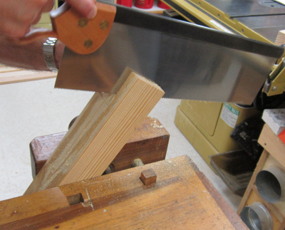
Here James is making the first
cut. |
 |
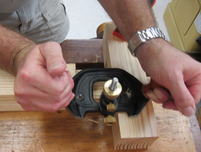
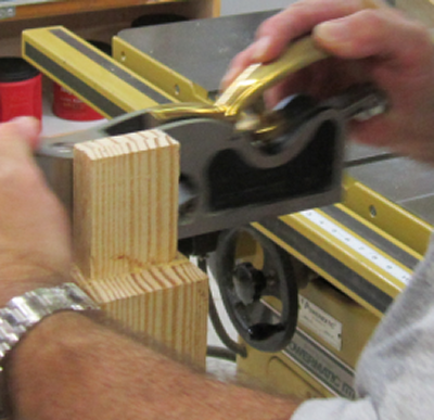
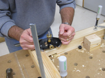
The cheeks were then finished
out to the proper dimension with a Veritas router plane. |
 |
Shoulders were squared with
Lie-Nielsen small and large shoulder planes. |
 |
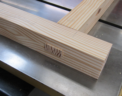
Here is the finished tenon. |
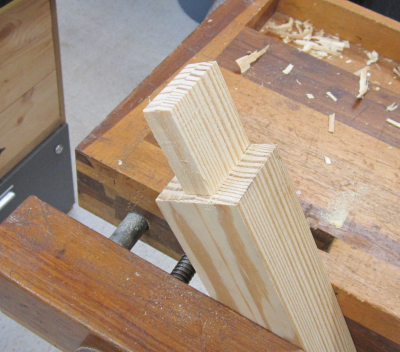 |
Considering that this was the
first tenon James and I ever created using hand tools...we were pleased
with the outcome. |
 |
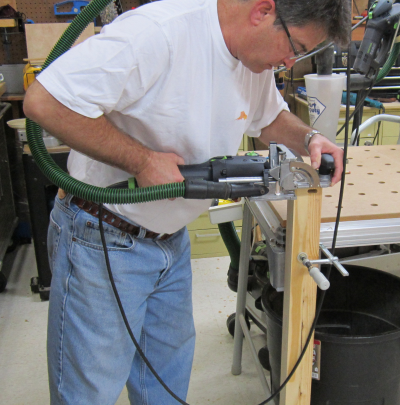
For the next step we went back
on the power grid...the matching mortise was laid out and then the majority
of the waste was removed with a Forstner bit at the drill press. |
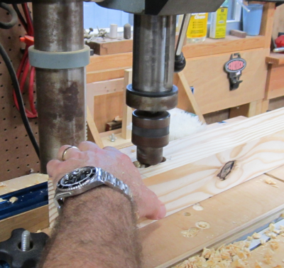 |
The mortise was drilled out
through the entire leg to accept the through tenon. |
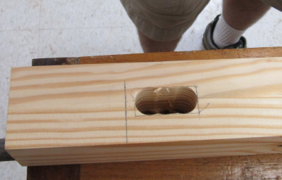 |
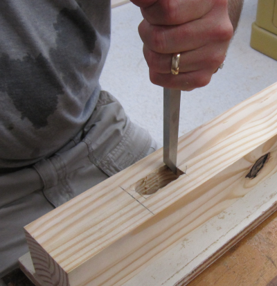
The waste was hogged out with mortise and bench chisels. Then the sides were evened out with paring chisels. |
 |
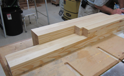
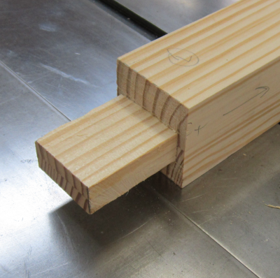
Here is the dry fit joining
of the stretcher tenon into the leg mortise. |
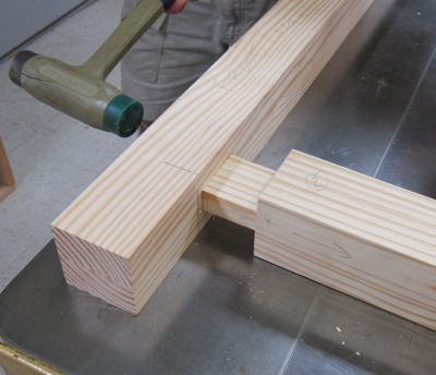 |
| A nice tight fit. |
 |
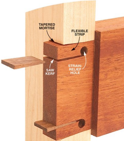
Because we are going to wedge the through tenon, the next step was to taper the mortise sides. Example diagram: shows how the tapered mortise allows space for the flexible strip to migrate into and thus tighten the joint. |
 |
One end of the shop-built mortise
paring jig was beveled at four degrees. |
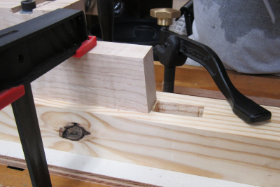 |
This allowed the jig to provide
an accurate way to bevel the side of the mortise. |
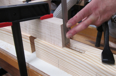 |
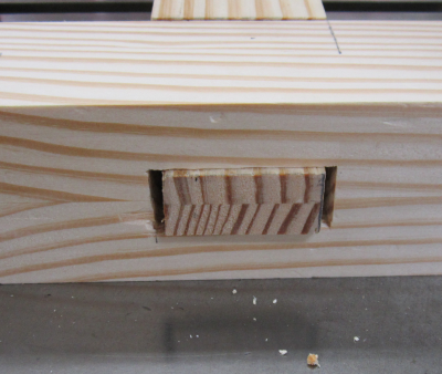
This created the tapered mortise that will allow the wedged tenon to expand and lock the joint. |
 |
Upper stretchers were cut to
exact measure... |
 |
Upper strechers are attached
with floating Domino tenons |
 |
All side tenons were cut and
then routed with Veritas plane for insertion into blind mortises. |
 |
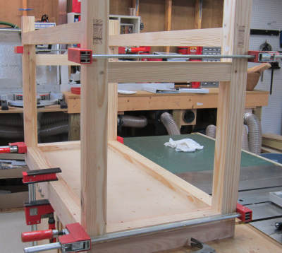
After cutting all of the tenons
and hogging out the mortises we did a dry fit. Here are the long stretcher
assemblies. |
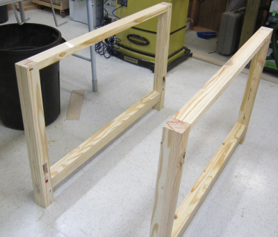 |
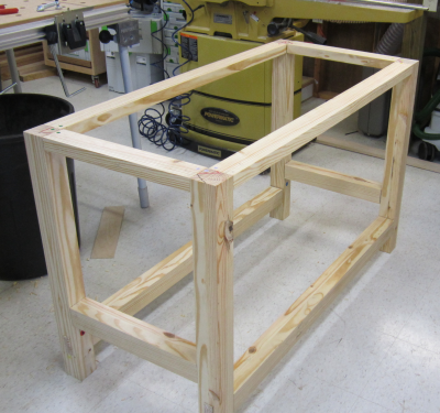
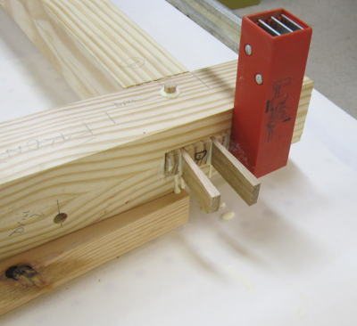
Full dry-fit assembly of the base section. Top stretchers are joined with floating Domino tenons. Short side stretchers are blind tenons and will have drawbore pins. Long stretchers are through tenon and will be wedged in addition to having drawbore pins. |
 |
Final assembly phase began with the layout of all of the drawbore pin holes, relief holes and relief kerfs for the tenons on the long stretchers. The short stretchers only needed drawbore holes. Hardwood drawbore pins and oak wedges are also shown in the image to the right. |
 |
After the drawbore pin hole is drilled in the leg, the center is marked on the tenon. Then the hole in the tenon is actually drilled 1/8 inch closer to the shoulder. Then the LN drawbore pin is used to line these holes up as best as possible. |
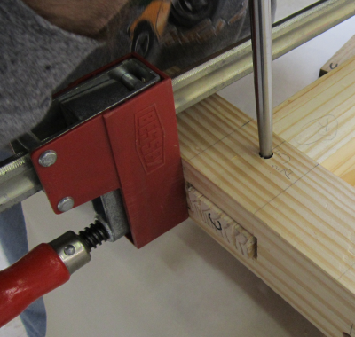 |
The drawbore dowel is then pounded
into the hole and as it goes through the joint it draws the joint tighter. |
 |
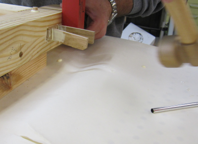
Then the oak wedges are pounded into the relief kerfs in the through tenons. As the flexible parts of the tenon are expanded they fill the spaces that had been created when the sides of the mortise were beveled 4 degrees. |
 |
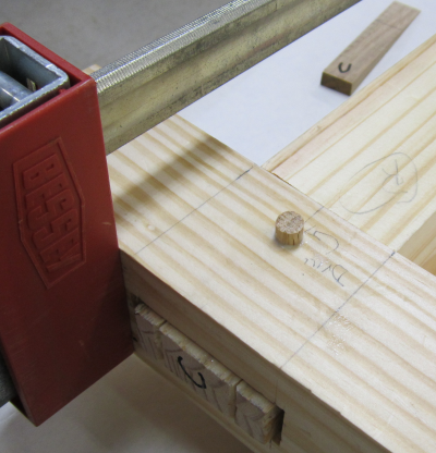
Here the drawbore dowel and
wedges have been installed. |
 |
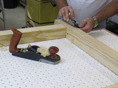
After the glue has dried, the dowels and wedges were cut off flush with a Japanese saw. Then block planes and smoother planes were used to freshen up the joints. |
 |
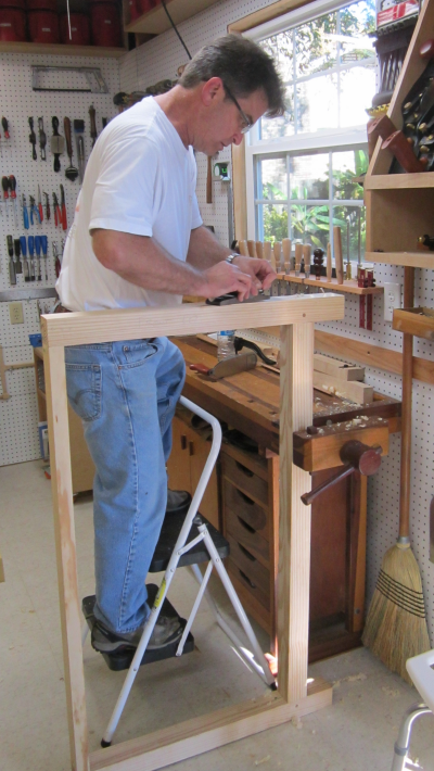
A little elevation was necessary
to comfortably plane the legs. |
 |
Final glue up with upper and lower short side stretchers added.
|
 |
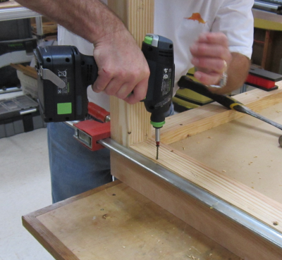
The base was screwed into the underside of the top. No glue was used in this step in case we wanted to change out the entire top at a later date.
|
 |
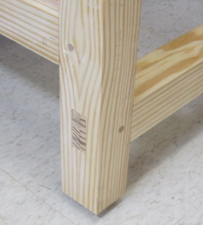
Closeup of the drawbore dowels
and the wedged through tenons. |
 |
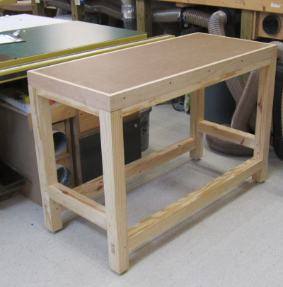
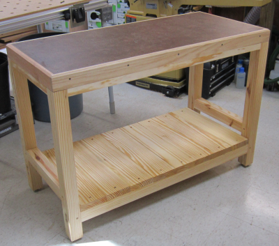
The final assembly. A lower shelf will be added later. |
 |
The work surface...with the final touches...chamfered edge on the oak trim...a coat of BLT rub on the unit.
|
 |
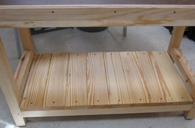
The lower shelf pieces were
milled to square edges and had the edges chamfered. |
 |
The finished product. |
 |
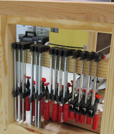
Addendum: After some use we decided to add a clamp rack on the end. |
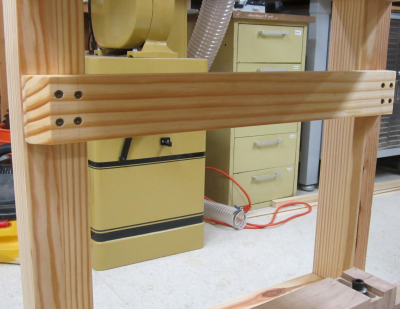 |
The board was mounted on the inside edge of the legs so that the clamps would hang inside the co-planar edge. It easily holds (R to L) four Bessey 6 inch clutch bar clamps plus 4 @ 6 inch and 6 @ 12 inch Bessey Tradesmen bar clamps.
|
 |
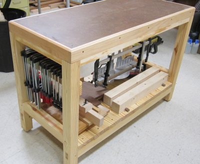
The assembly table in use with
a full clamp rack and plenty of storage on the lower shelf for jigs,
appliances and the Nobex Champion mitre box. |
 |
Addendum 2: After a couple of years, I concluded that the clamp rack worked great until the table was moved and that I moved it fairly oftern. I had originally opted not to have a design that held the clamps in place so that I had more options. However, that meant that clamps would a have a tendancy to fall during the move. |
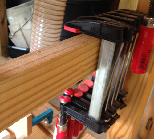 |
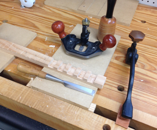
Additionally, I felt that I would continue to keep the 12 clamps that were housed there and that I should make them more stable. I decided to add a crenalated spacer to the rack on the end. Here I am testing the spacing so that the clamp will be held securely but not fight with the other clamps of its size. |
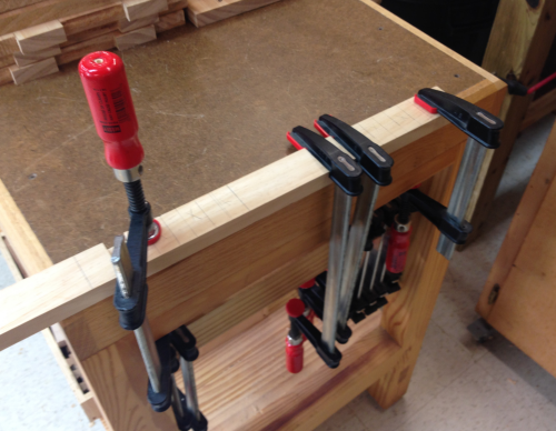 |
I eventually decided on 3/4 slots to hold the clamps with 1/2 spacing in between. The depth was marked off with a Tite-Mark and then I crosscut to that depth with a carcase saw. |
 |
I then chiseled the slots and finished them off with the large LN router plane. |
 |