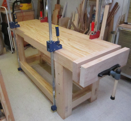
The Finished
Workbench |
 |
 |
 |
 |
 |
Workbench Project The planning stage of the new workbench has been quite extended. Starting 20 years ago I would spend countless hours poring over Scott Landis' "The Workbench Book". I have used a succession of workbenches... Black & Decker Workmates (2 different models), sawhorses and sheet goods, a metal cabinet with shop-built top, a recycled bowling alley lane workbench with metal vises, etc. I used a light-weight Scandinavian style cabinet worker's workbench for many years...it was helpful but simply too light. A few years ago I got a Festool MFT3 table and though it is super versatile, it also is simply way too light. My thoughtful transition to using hand tools has given me cause to need a heavy-duty bench that can hold a piece of wood along any edge, face, end etc. so that it can be planed, sawn, chiseled, etc. So, the decision to build this bench was made. To make sure that I had the right design for the bench, I
read numerous articles around the Internet and went over back issues
from my Fine Woodworking and Popular Woodworking archives. James, my partner in wood working crime, and I spent many hours thinking and rethinking the many elements...design, wood choices, joinery skills needesd, tools needed, etc. The design phase is ending...and the construction is about to begin.
|
|
|
I have often looked with great awe at the massive
|
|
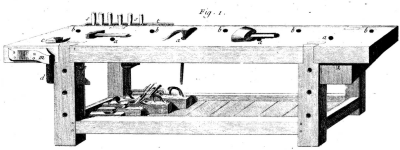
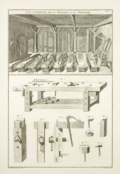
In my office I have a framed poster of Plate 11 from Andre Roubo's 18th century masterpiece "L'Art du Menuisier". This plate is titled "Vue Interieure de la Boutique d'un Menuisier" ..."interior view of the shop of the craftsman". There is great detail in the bench and the bench hardware at the bottom of the plate. |
 |
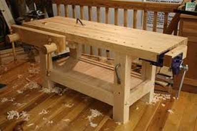
James and I took some design
elements from the Roubo bench and some elements from the Holtzapffel
workbench. The Internet image shown to the right is pretty much the
unit we conceived...except for the changes shown below. |
 |
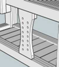
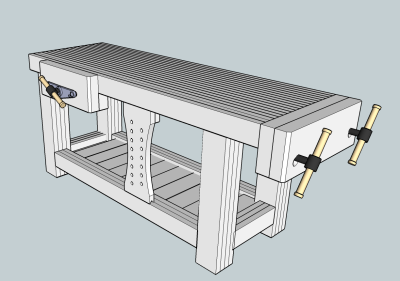
We decided to throw the twin screw vise to the end and put a single quick release vise on the front. There is also a "sliding deadman" in the front. This is the preliminary Sketchup design of the bench unit. It will be about 24 inches deep, 77 inches long and 31 inches tall. |
 |
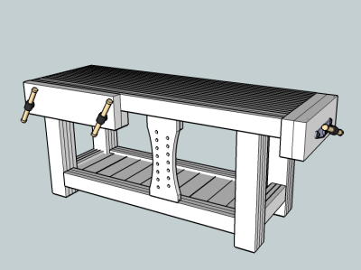
After ordering and receiving the Veritas vises from Lee Valley, we examined the hardware and we reconsidered the vise locations. We decided to put the quick release on the end and extend the the chop and jaw to 23 3/4 to cover the entire end. We moved the twin screw to the front, aligned it with the left end, moved the handles to 24 inches on center to make use of the full width of the unit and extended the jaw to run 30 inches. |
 |
Chris Schwarz' book had a lot of great information...but the greatest lesson I took from the book was that the designer/builder needs to decide what he specifically wants in his particular, personal bench. Schwarz provided a great road map for creating a proper design...it involved "18 Principles" to consider... listed below are the items he suggested for consideration and our decisions |
 |
#1 always overbuild the bench, the base… |
5 x 5 legs; 4 x 3.75 stretchers, plus shelf
and deadman |
#2 always overbuild the bench,
the top... |
slab is 4 inches thick, 72 long, 23 3/4
wide |
#3 question unusual designs |
design is based on classical types |
# 4 a bench cannot be too heavy
or too long, but the top can be too wide |
depth = only 23 3/4 inches |
#5 choose the right height,
lower is better |
after many trials using a variety of tools,
seated and standing, etc. we settled on 33 inlches |
#6 choose a good spot for the
bench to live |
on the southeast wall...all sources recommend
natural light so we are going to put in a window unit right over the
bench |
#7 you should be able to move
your bench, but not too easily |
unit will be stout but moveable, legs will
have chamfered edges to make sliding easier and less damaging |
#8 make clamping easy, everywhere |
this is a major priority, we designed a
co-planar front with plenty of good clamping access |
#9 you must be able to grip
wood to work on the faces, the ends and the edges |
also a major priority...with the vises selected
plus deadman and the hold down hardware all types of griping will be
achieved |
#10 aprons and skirts issues |
top is a slab...there will be no apron |
#11 front edges all co-planar |
Co-planar |
#12 tool tray...yes or no? |
no tool tray |
#13 select best available, inexpensive
material |
yellow pine top and base; hard maple jaws
& chops |
#14 forget showy |
we went for stout, durable, functional,
excluded pretty |
#15 vise options |
Veritas Quick-Release end vise Veritas Twin-Screw front vise, 24 inch center |
#16 dog holes...square or round |
opted for round...there is a wide range
of 3/4 round hole clamping devices available |
#17 storage decisions...shelves,
drawers, tool trays, etc. |
one lower shelf |
#18 finishing |
linseed oil thinned with turpentine, plus
a protective thinned varnish |
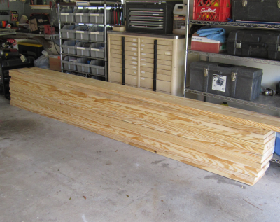
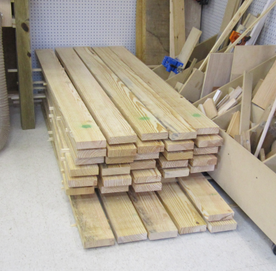
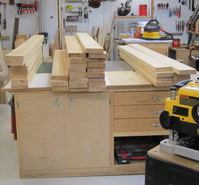
The yellow pine purchase was made after checking all the local big box stores to find the best selection of dry lumber. We bought 2 x 12 x 12 boards because the larger boards typically have fewer flaws than the smaller boards. Because the turnover rate is lower they are typically dryer as well. I found the best batch and we purchased fourteen units. This is enough material so that we can minimize problems. We also plan to make an assembly table and two saw benches out of this same batch. Here are the boards in temporary storage in the garage. |
 |
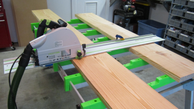
The boards were cross cut into either 6 foot long or 5 and 7 foot long batches. This was done in the garage using Festool equipment on the BenchMark cutting table. |
 |
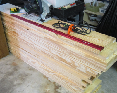
After the cutting session I now had a taller stack of shorter 2 x 12s. These had to then be hauled to the shop and then taken into the attic for storage. |
 |
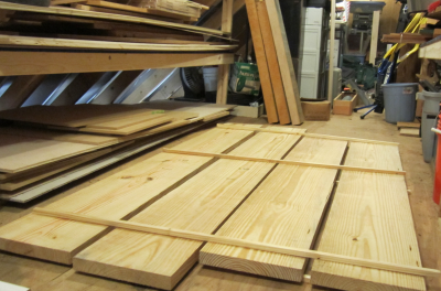
Here is the first layer of the yellow pine storage stack in the shop attic. Boards are stacked 4 across on stickers for air flow. These boards are being stored for climate acclimation. The hard maple slabs can be seen at the rear of the stack. |
 |
Here is the full load in storage. |
 |
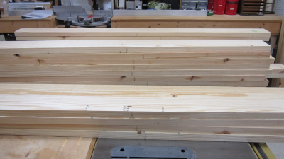
After the stack of 2 x 12s had
seasoned in the attic, they were moved downstairs to the shop. After some assessment, the boards were ripped in half and stacked on stickers in the corner of the shop. |
 |
The stack then seasoned in the
shop for about a month. This made the "stack in the corner" suddenly become a hole... |
 |
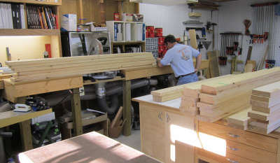
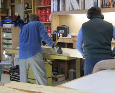
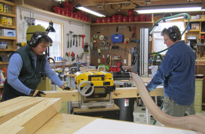
After we jointed each piece on the Powermatic...on average, at least four passes each board ...we marked the board and put it in a stack as to purpose...legs, stretchers, and top.
|
 |
After a hard day of heavy lifting
and multiple passes we had three stacks of jointed boards ready for
the planer. |
 |
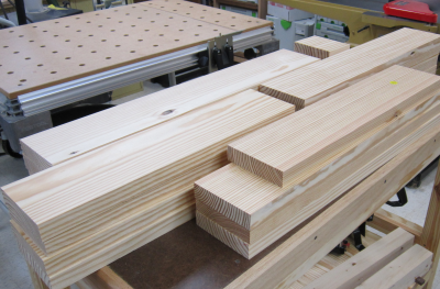
On the second day we planed the other face to a final dimension of 1.25 inches for all of the stock. The remaining edge will be ripped to arrive at the final width dimension based on whether it will be used in a leg, a stretcher or the top. |
 |
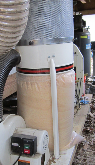
In two days we milled enough
wood...on the jointer or through the planer... to fill three bags with
chips. |
 |
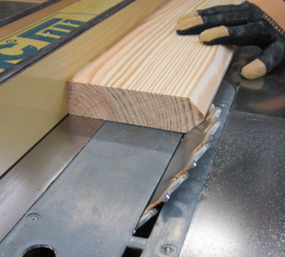
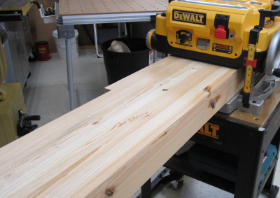
Most of the boards used in the leg and stretcher pieces will be ripped to the same dimensions. The one exception is the front piece of the front stretcher had to be bevelled because the top of the piece will be the runner for the Sliding Deadman.
|
 |
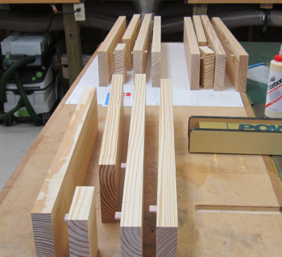
Here are all of the milled units
for the legs and stretchers. |
 |
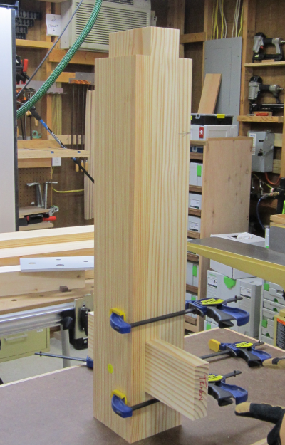
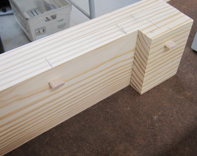
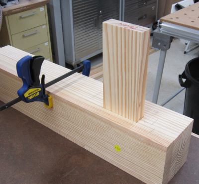
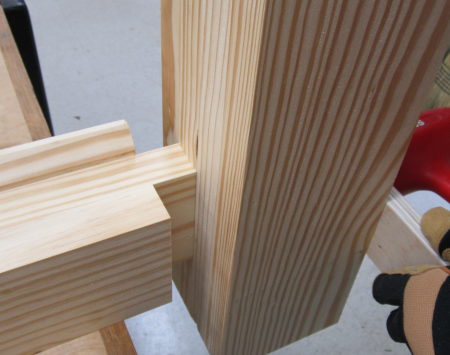
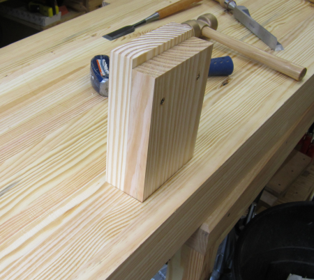
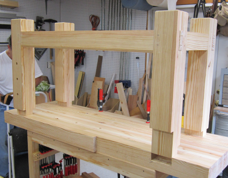
A dry run mock up to make sure our design for the through mortise worked out ok...it did. The top of the leg has a 2.5 inch by 5 inch tenon. It will mate with a mortise in the underside of the bench top slab. |
 |
We put in Domino tenons to use
as index points for the leg glue up. |
 |
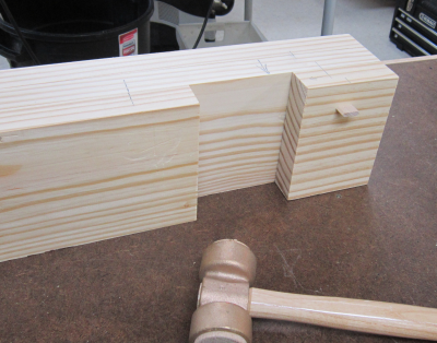
Here is the way that the through
mortise is created in the glue up stack. |
 |
The full leg mock up with a
test fit of the tenon model. |
 |
This is a dry run of the the four layer 5 inch leg with the three layer 3.75 inch stretcher.
|
 |
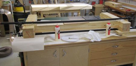
Leg Glue-Ups After testing all fits it was timeto glue up...James had built two glue-up base units. They will hold the slabs off the assemby table.
|
 |
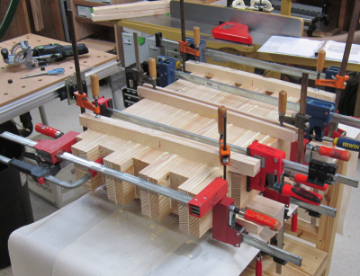
All four leg units will be glued-up and clamped at the same time. Large Bessey clamps will be paired top and bottom at four structural points to apply pressure from side to side. Three clamping cauls will hold the pieces in place top to bottom. |
 |
Here are three leg units broken
into segments that will be added board by board to the stack and then
glued. |
 |
All four leg units are in the
clamp stack. |
 |
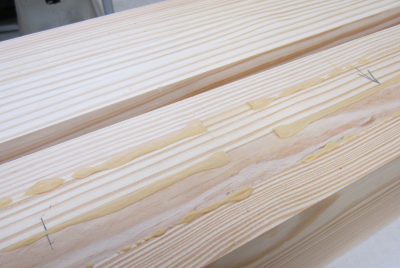
When the legs came out of the glue-up stack there was substantial dried glue trails that were squeezed out by the clamps. These were lightly cleaned up by chisel and plane and then the face was jointed on the Powermatic. A clean face is shown on the top.
|
 |
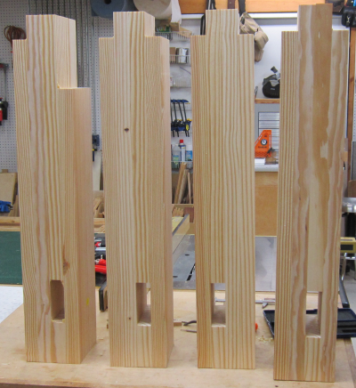
Here are the four legs. Each has a mortise ready for the front and rear stretchers. The far left shown is the front left leg. It has a short shoulder on the front face to accomodate the 8 1/8 inch hardwood vise chop.
|
 |
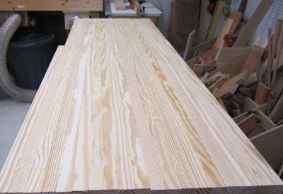
Top Sections Glue-Up After the 19 boards that will make up the top had been milled and ripped, they were sorted to provide optimum grain pattern, knot avoidance, etc.
|
 |
The glue-up process will be done
in three stages. From front to back there will be a 5 board, 5 board,
5 board and 4 board sub-assembly. Here is the beginning of the first glue up. The four sub-assemblies will all be in the clamped unit but each sub-assembley will stand alone. |
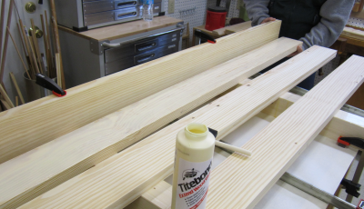 |
Even though we were using Titebond
slow set glue, there was still a need to proceed quickly. We started with light pressure on the underneath Bessey clamps and then lined up the top edges with three caul units. The outer cauls were shop made and the center is a Bowclamp. |
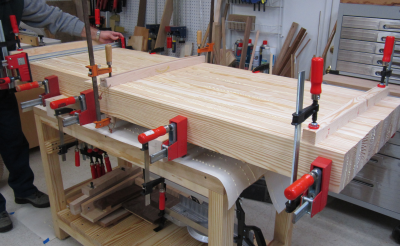 |
Adding pressure across the top of the assembly. The glue drip out was substantial.
|
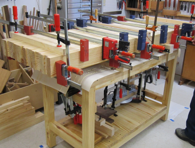 |
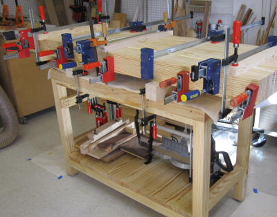
The full glue-up stack. |
 |
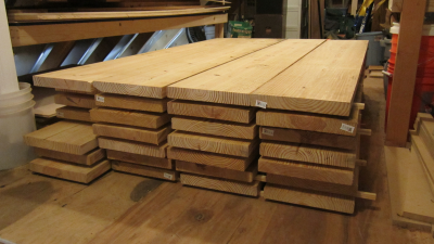
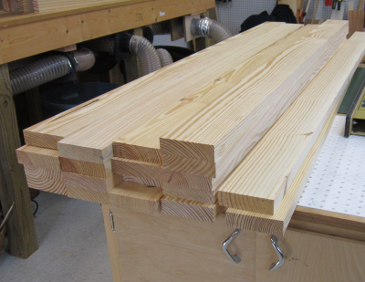
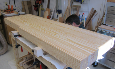
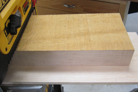
After a night of set-up and then clamp removal, the four sub-assemblies provide a glimpse of how substantial the top slab will be. In this view it is easy to notice the front board which is only 42 inches. There will be a 30 inch inner vise chop that will be made of hard maple. It will fill the space at the left end of the front of the bench. |
 |
Long view of the top. |
 |
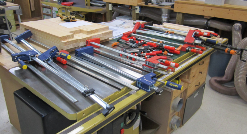
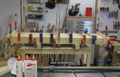
In homage of the adage..."you can never have too many clamps..." This glue-up took...four 6 inch Bessey bar clamps, six 12 inch Bessey bar clamps, four 24 Jorgensen bar clamps, one Jorgensen pipe clamp, five 24 inch Bessey K body clamps, two 24 inch Irwin parallel clamps, one 24 inch Bessey Revo clamp, two 28 inch Irwin parallel clamps, two 48 inch Bessey K body clamps, two shop made cauls, one Bowclamp caul, and two shop made spacer bases. The glue drip clean-up on these units will take awhile...plus the temperature at the time of this picture was ~27 degrees...all that metal will be cold.
|
|
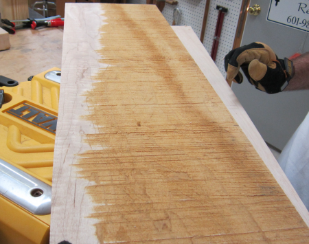
After removing the clamps, we cleaned up the glue lines and then jointed the top surface of each of the four units. Then we carefully squared the adjacent face that will be a glue surface in the next step. Here we are pushing a five-board slab across the jointer. |
 |
Then the sub-assemblies were surface planed to dimension. In this image, a four inch thick sub-assembly is being worked through the planer. We filled another couple of chip bags on the day. |
 |
The four sub-assemblies are checked for thickness consistency.
|
 |
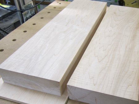
These four units are then glued into two slabs. In comparison to the previous glue up, there were only two glue lines so it went very quickly and there was very little time pressure. Later in the day (~5 hrs of drying time), we were able to pull off the clamps.
|
 |
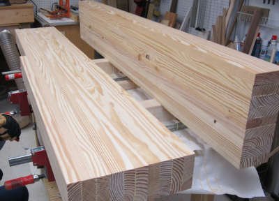
The two half-top sub-assemblies were then surface planed to clean up the glue lines and make both slabs have a consistent thickness. The slabs were now 12+ inches wide so we were no longer able to joint them on the Powermatic. We were just able to surface plane the sub-assemblies in the DeWalt.
|
 |
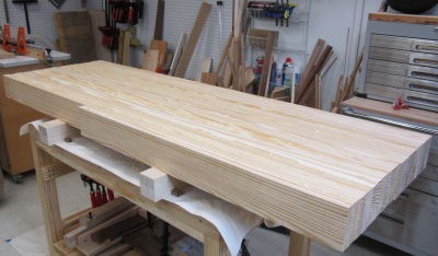
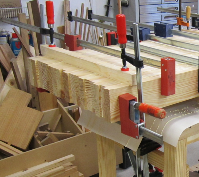
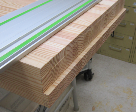
The final glue up converts the
two units into a single 23.25 inch. This is a 19 board lamination. |
 |
The length of the slab will be trimmed to ~71 inches to make the ends even.
|
 |
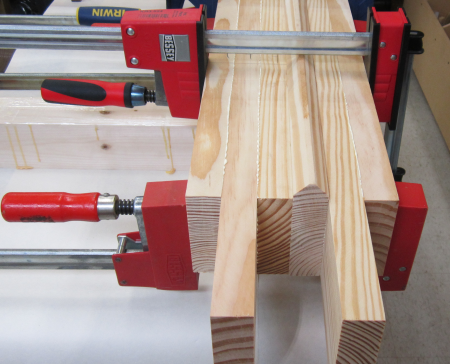
Stretchers glue up The last stage of gluing was the two long front and back stretchers and the two shorter side stretchers.
|
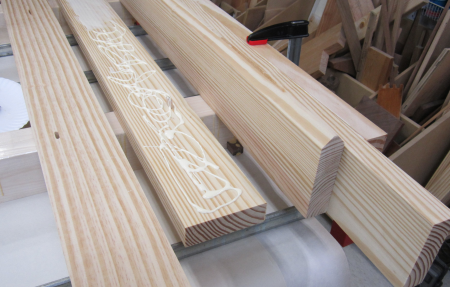 |
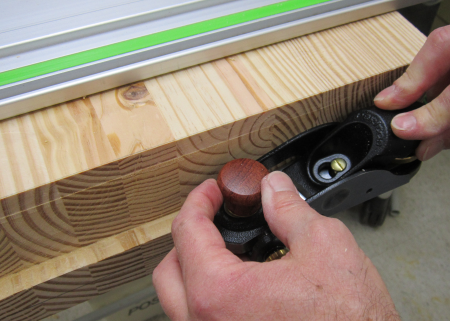
After drying, the stretchers would be machine jointed and planed to final dimensions. The one exception was the top of the front stretcher. Due to the bevelled top edge of the stretcher that will be the rail for the Sliding Deadman. The top of this stretcher was planed with a #6 fore plane. |
 |
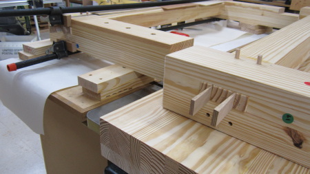
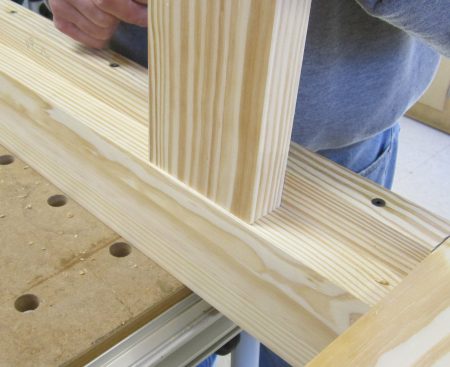
Base construction began with test fits of the stretcher tenons into the leg mortises. Here the first fit is a nice tight joint. |
 |
Outside edge view of the through tenon. This edge will be chamfered and sit about 1/8 inch proud after the draw bore pins and wedges are pounded in.
|
 |
Minor corrections were made
with chisels or planes. Here a skew block plane is used to clean up
the joint. |
 |
This shows the draw bore pin
holes through the mortise opening. |
 |
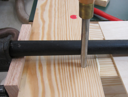
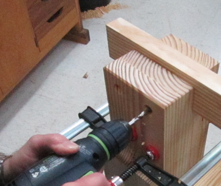
Here is the drilling out of the 3/8 drawbore pin holes. The outside holes were done on the drill press for precision. The matching hole on the backside of the mortise was done with a Festool hand drill. |
 |
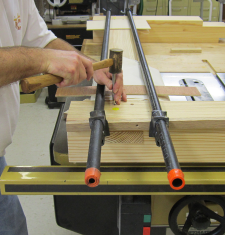
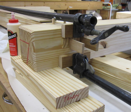
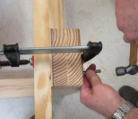
After the drawbore pin holes were drilled, the tenon was pounded back into the mortise and pulled tight with long bar clamps. Then the drill bit was placed in the hole and tapped with a hammer to make a precise mark on the tenon. |
 |
Here is what the marks looked
like... |
 |
Then the center mark was moved 1/8 of an inch in toward the shoulder and the holes were drilled into the tenon. At glue up... the drawbore pins are pounded through the holes on the outside face of the leg, then through these holes in the tenon and then finally into the holes on the backside of the mortise. This action will align the holes somewhat and thus draw the joint tight. |
 |
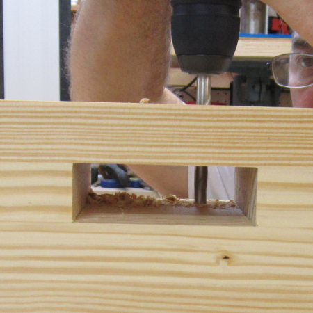
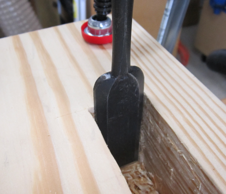
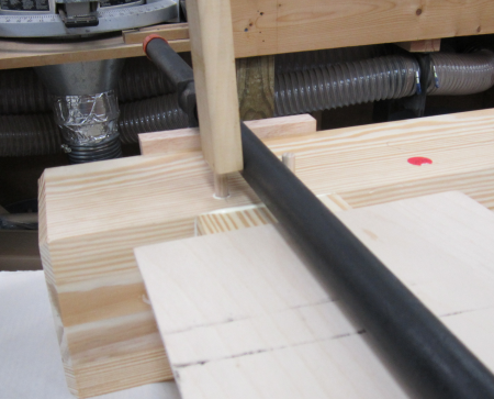
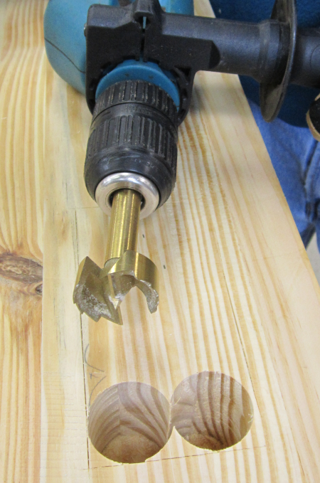
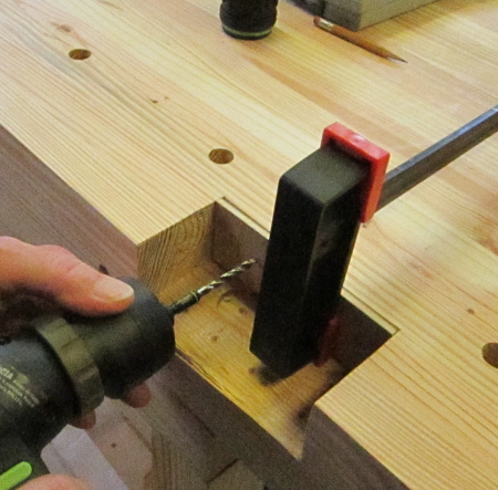
Next step was to make the mortises for the side stretchers. The stretcher tenons and mortises were create by design during glue up. These mortises had to be laid out and then material removed. The depth of the mortise would break out into the space of the existing through mortise. After layout, most of the material was "hogged out" using a 1 1/4 inch Forstner bit on the drill press. First a hole was bored at each end of the mortise. |
 |
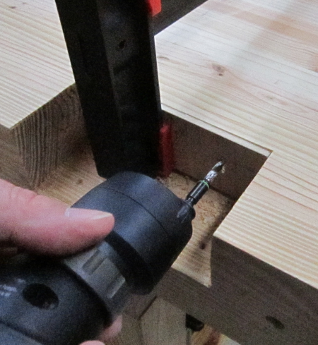
Successive bores are made between the first two holes. This leaves some side material to pare down and the corners to be squared. The bottom of this hole is a "sacrificial" tenon that allows the bottom of the mortise to be formed without spelching into an open cavity. This tenon is removed after drilling and chiseling. |
 |
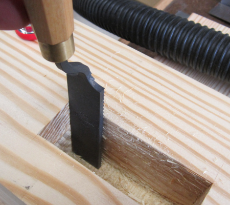
Here is image of paring work with a large becnh chisel Sacrificial tenon is seen at bottom right. |
 |
Corners were beaten out with a large Sorby corner chisel. James was particulary fond of the powerful pounded function of this massive chisel. |
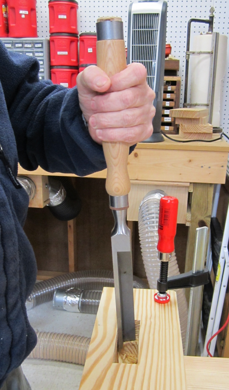 |
A wide variety of hand tools and techniques are used to get the mortise right. My favorite tool in this process was a Nishiki Kinari Japanese paring chisel. |
 |
Rough sides were smoothed out
with a LN mortise float. |
 |
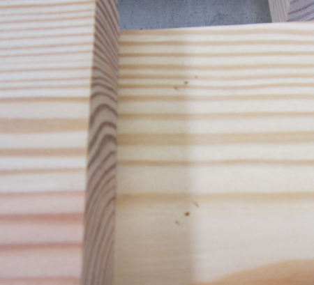
End result was nice tight fits. |
 |
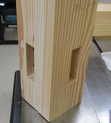
Now all four legs had both mortises
in place. |
 |
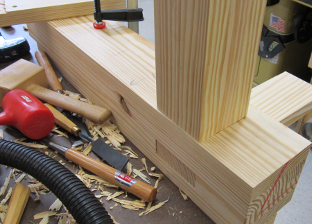
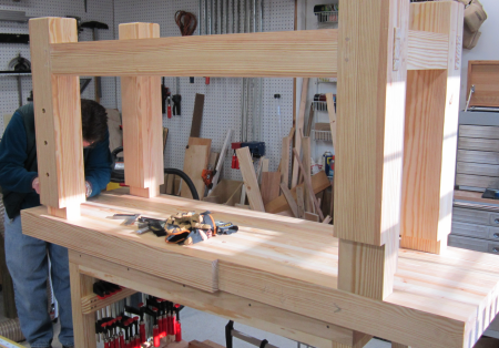
Here is a dry run of the left
end of the bench. Because it is so easy to get disoriented dealing with
so many faces, after the dry fit we marked the joints with colored markers
to help rejoin them later. |
 |
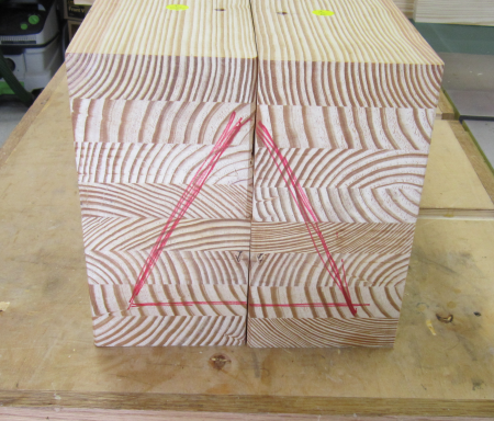
Early in the process we had laid out all four legs in an easy orientation stack and then marked the bottoms of the legs with a red triangle. Between most steps we restacked and verified the triangle as a way to reorient all the faces. |
 |
In preparation of the glue-up,
we chamfered all four edges on the bottom of the legs to reduce tear
out when moving the finished bench. |
 |
Bottoms of the legs ready to go.
|
 |
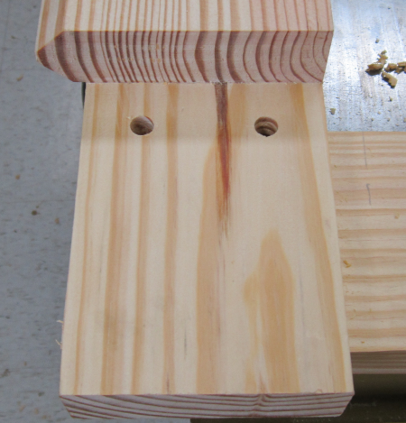
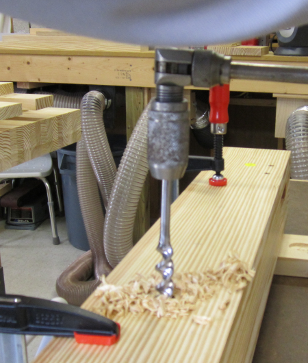
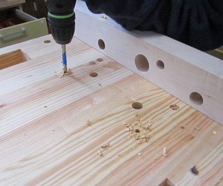
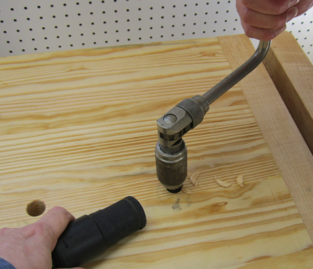
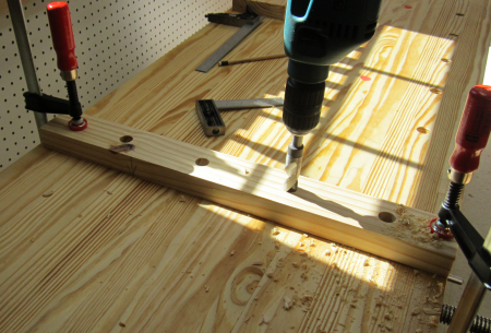
A final step before the legs are ready for assembly...the front right leg face is to have three dog holes for use with hold-downs. The five inch thick leg had the holes bored with a 3/4 inch auger. The worker had to stand on a step ladder to gain elevation for the work.
|
 |
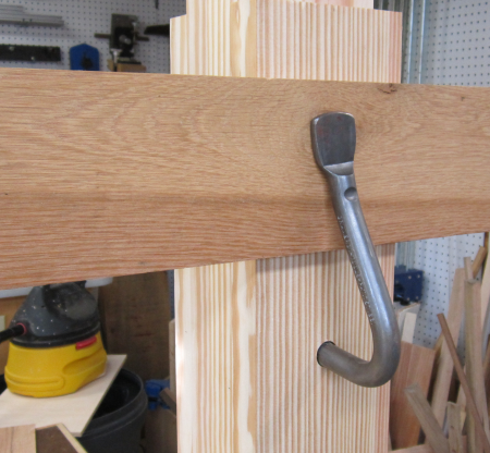
A quick check that the hold-down
works well in the bored holes. |
 |
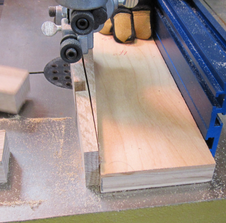
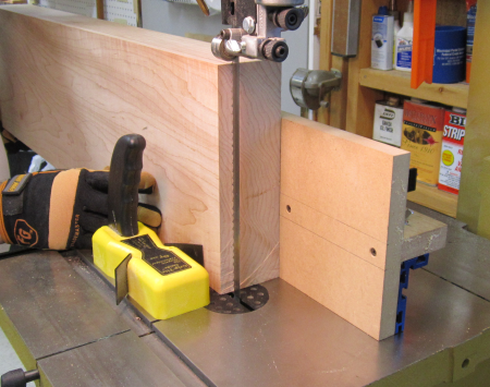
Final prep for glue ups...we
cut 4 degree wedges using a jig on the bandsaw. |
 |
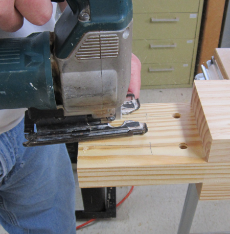
Kerfs to receive the wedges
were laid out and cut with Bosch jig. |
 |
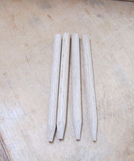
Oak dowel stock was pounded
through the LN Dowel Jig and sharpened in a pencil sharpener. Here are
the four draw bore pins. |
 |
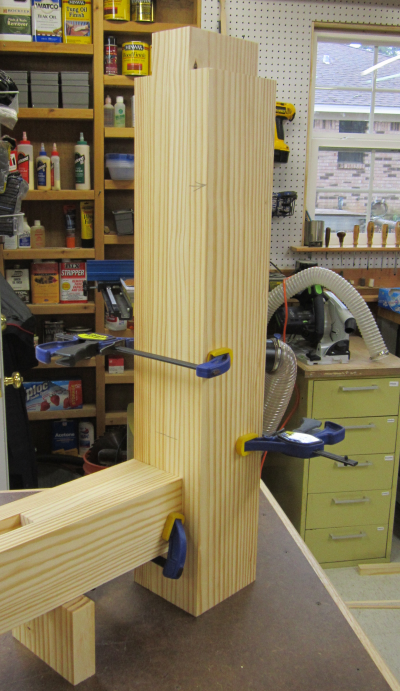
The long stretcher was glued
and then pounded into the legs for the final time. Pipe clamps tightend
the joint and then a LN drawbore pin was inserted to try to align the
holes as well as possible. |
 |
Then the pins were pounded in the holes.
|
 |
Wedges were pounded into the
ends of the through tenons. |
 |
Clamped unit dries up overnight. |
 |
Next morning, the first unit was removed and the second unit was assembled in the same manner, then clamped and glued.
|
 |
Before gluing up the final base assembly a ledger board was screwed onto the inside faces of the long stretchers. This will later accomodate the lower shelf slats. |
 |
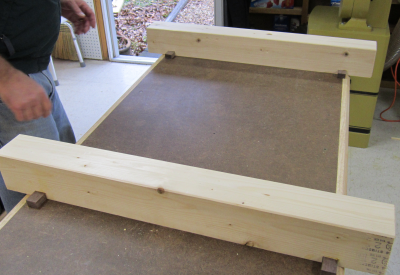
View of the glued and clamped base assembly. This view is of the rear of the workbench.
|
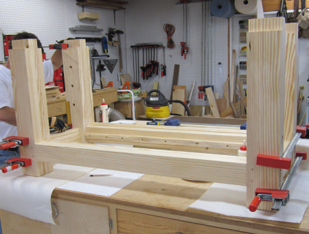 |
The left end view. |
 |
The front view. The slab top assembly is in the foreground. The next phase will be placing the base on top of the underside of the top assembly and marking the layout for the final four mortices. |
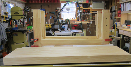 |
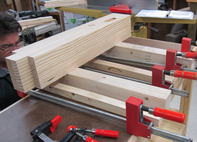
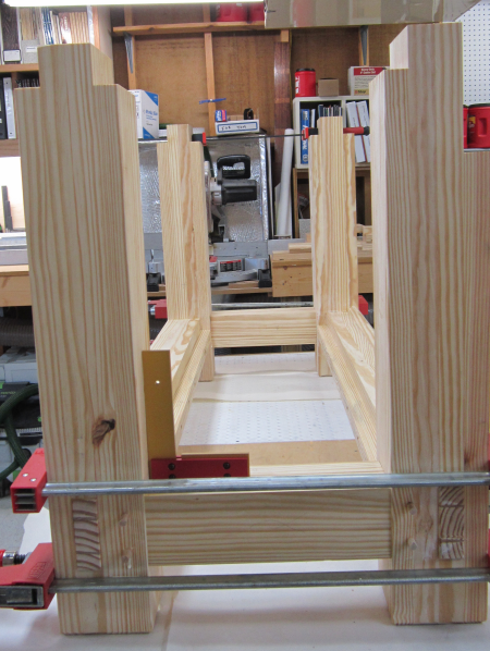
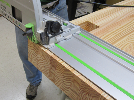
After the final glue-up, the full slab was moved to the Festool MFT3 table. We had to make a clean cut-off on each end of the slab. |
 |
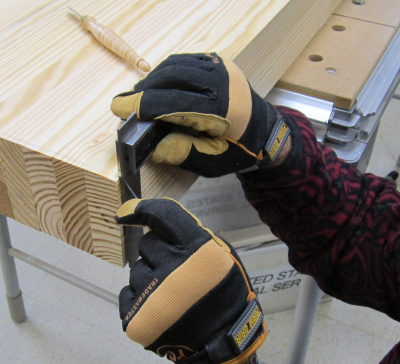
We carefully marked the square
edge with a marking knife. |
 |
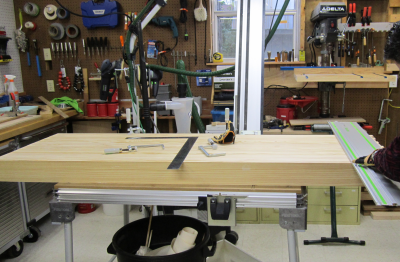
We then aligned the Festool saw guide rail to those knife nicks.
|
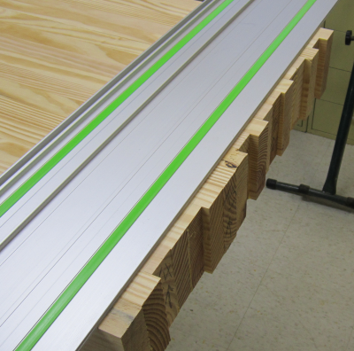 |
The first pass was made to the
fullest extent possible. On the TS 75 this is approximately 70mm (2
3/4 inches) deep when the saw is resting on the cutting guide. |
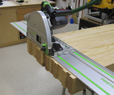 |
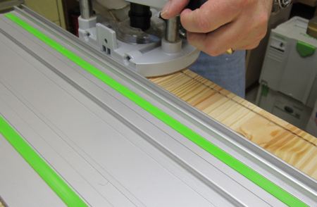
The second pass was made at
a depth of 40mm (~ 1.5 inches). The height of the slab on the MFT3 table
meant a step ladder gave a better and safer cutting angle. |
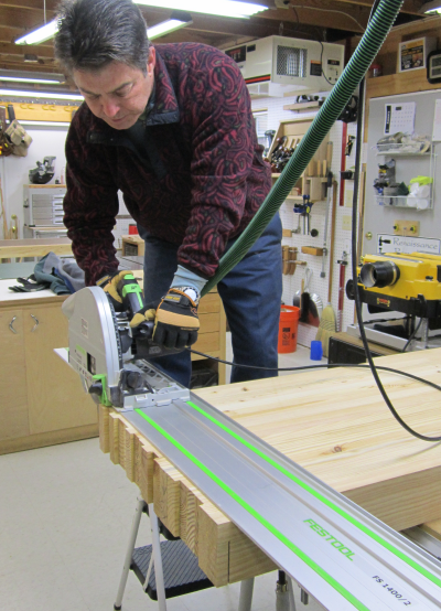 |
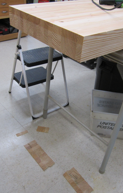
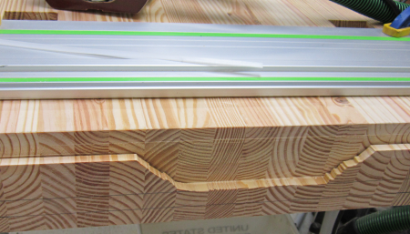
The second pass was made from the bottom side and the result was a wonderfully square and even cut. We had been dreading this cut-off but it went well and we were very pleased with the results. The left end of the benchtop will probably be "bread boarded". The right end will definitely be bread-boarded by the inside chop of the single screw vise unit on the end of the bench. |
 |
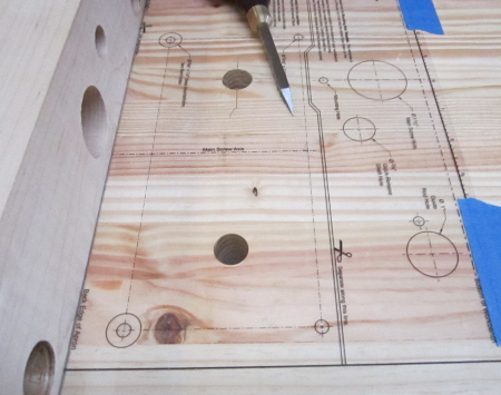
The next step was to mark out
the mortises on the underside of the top slab. These were 2.5 inches
by 5 inches. The base sub-assembly was laid on top of the slab and marked
out with a striking knife. The design had the front of the unit being coplanar and the rear of the base being inset about .25 inches. |
 |
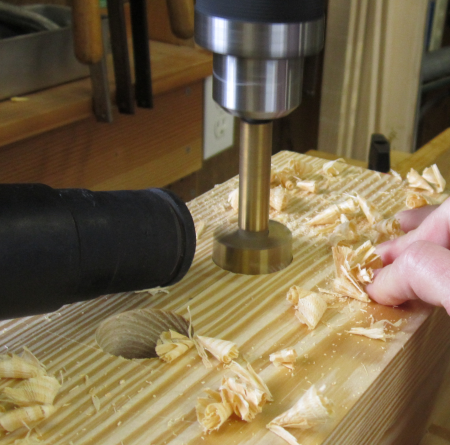
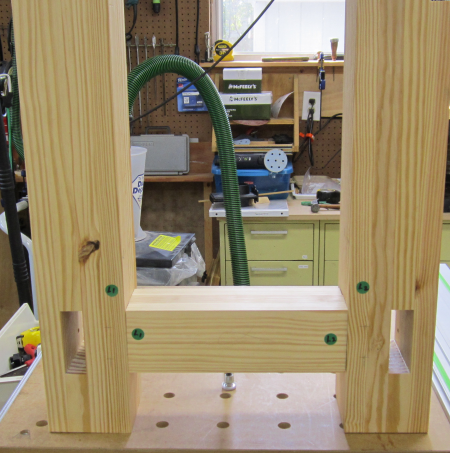
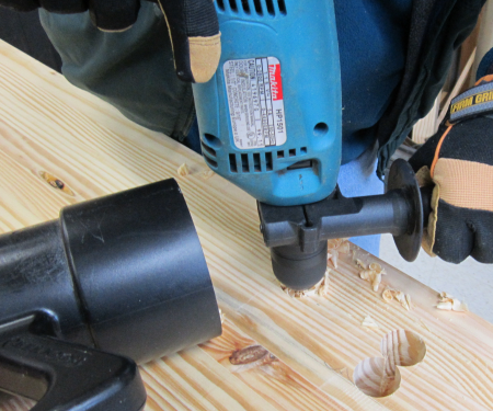
After layout we began the mortise process...starting with a 1.25 inch Forstner bit to hog out as much as possible. We used a Makita AC powered drill to increase power. It has a side handle that made it easier to apply pressure and to keep the unit square. |
 |
We used a 4 inch vacuum line
to pull away chips while drilling. |
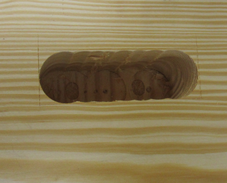
 |
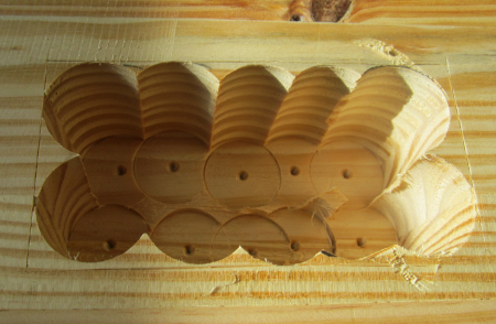
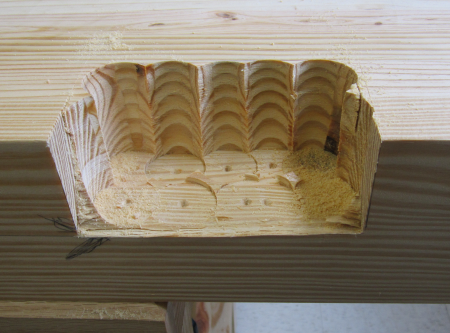
Here is a mortise after the
hog out. |
 |
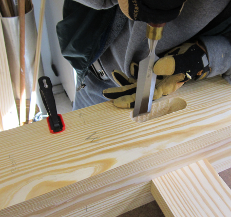
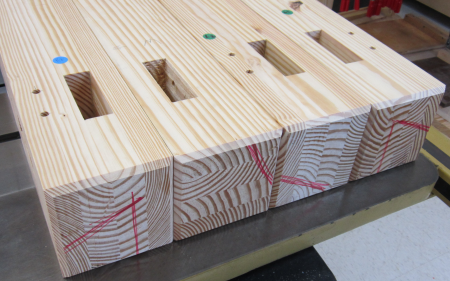
An array of bench chisels, paring chisels, corner chisel, mortise floats and various types of pounders were used to pare and square the mortises. This image shows the rear two mortises completed.
|
 |
Test fit with a tenon replica. Very tight, very square. |
 |
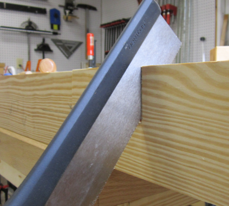
One of the mortises will lay behind the front vise chop. Thus it was created as an open mortise on the front edge in this setup. I used a Veritas cross cut back saw to cut out the thin wall on the forward edge. |
 |
Here is the open mortise waiting
to be pared and squared. |
 |
After all four mortises passed the test fit, we put the base assembly back on and pounded the tenons in about a half inch to make sure all was well. Unit was then pulled back out. Next will come the breadboard end treatment on the right end. |
 |
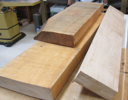
The vise chops will be make from hard maple. These 12/4 slabs had been brought to me from Virginia by my brother Tom. The end vise chops will be ~24 inches long by 7 inches wide. The inside chop will be 2 inches thick and the outside will also be 2 inches. Both of these chops will come out of the milled board on the right. The front chops will be ~30 inches long by 8 1/8 inches wide. Inside chop thickness = 1.25 inches and outside chop thickness = 2 inches. Each of the boards on the left in the image will produce one of the front vise chops. |
 |
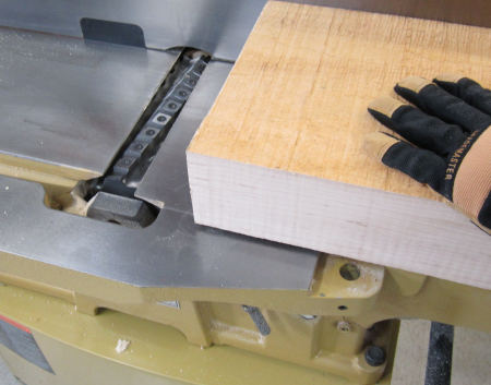
The 8 1/8 inch wide board posed a problem. This chop will be wider than the cutting head on my Powermatic. If we wanted to use the power tools, we would have to to use a workaround that we had read about. First we had to break all OSHA mandated codes and remove the protective cutting head cover...exposing ourselves to massive danger... We then ran the slab over the jointer numerous times until we had a nice jointed surface for about 7 1/2 inches of the board. |
 |
The board ends up looking like
this...a flat jointed surface for most of the width and then a protrusion
on the outside edge. |
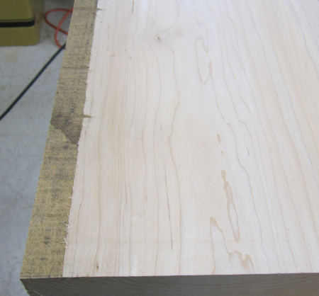 |
We then turned the slab over and placed the clean portion of the slab onto a 1/2 sheet of plywood. The protrusion is hanging proud on the far edge. Now we can plane a clean surface that will be parallel to the reference edge that we jointed. |
 |
Here is the slab as it starts to become planed smooth. After this face is done, we flip the slab and plane that side till the protrusion is gone. Those reference surfaces will go against the fence of the jointer and the edges can then be squared. |
 |
Here are the two slabs for the front chops. Beautiful wood. Thanks Tom... |
 |
To finish milling all chops we first resawed the maple slabs to rough thickness. We used an auxilliary fence and had the Powermatic cutting pretty much at it's max throat capacity. We then milled them to final thickness in the planer. The twin screw rear chop is 1.25 inches, all the other jaws are 2 inches thick. |
 |
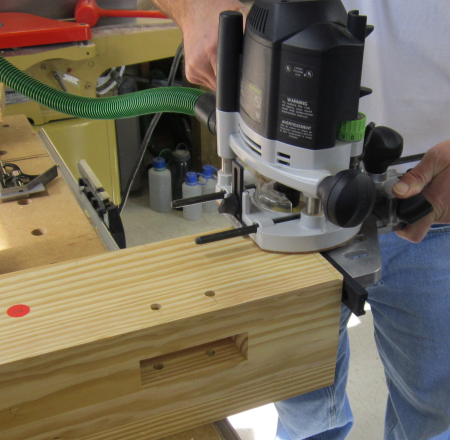
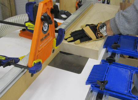
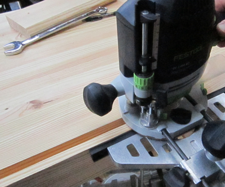
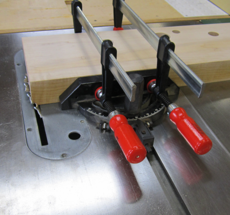
We then began the process of the breadboard end of the workbench. The tenon is to be 3/4 inch by 1/2 inch. We decided to use the T75 track saw to cut a kerf to define the line. We used the 1/2 depth kerf to practice on the bottom. The top kerf on the top surface of the slab will be that 1/2 inch...the bottom will be much deeper.
|
 |
We then routed the waste. This gave us a nice clean look when we tested the process on the bottom side. |
 |
However, when we cut the final depth of the kerf (~2.5 inches) on the bottom and then started routing away the waste, we had a major blow out. We totally underestimated the powerful torque of the OF 1400 router and when it grabbed on a glue line it ripped off a huge chunk. The end sliver was vulnerable because it was unsupported after the deep kerf cut. Fortunately the blowout went down only as far as our tenon edge. |
 |
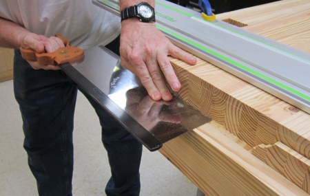
To fix the issue we temporarily screwed on a ledger board that defined the tenon edge. I then used that horizontal platform as a guide for the Bad Axe 16 inch tenon saw. This massive back saw is filed to a 12 ppi hybrid cut that did a good job on all the end grain and was the perfect tool for the job.
|
 |
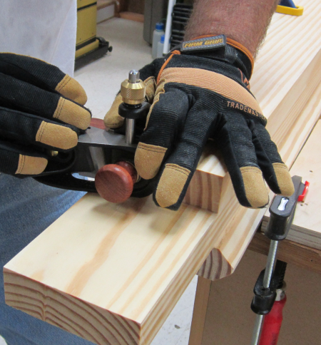
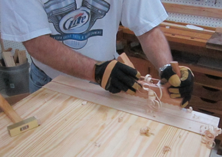
We then used a skew block plane
to clean up the blow out edges and the saw marks. |
 |
Living up to a personal philosophyof life..."I screw up a lot, but I recover nicely"...we did recover well. The bottom, deep cut is done...now to flip and finish with saw kerfs, chisel and skew plane. |
 |
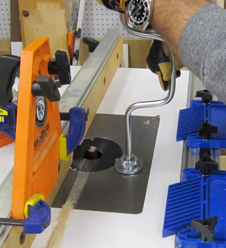
After the tenon was cut, we had to route the 3/4 groove that would serve as the mortise. It was a stopped mortise so that the front edge would be clean. To accomplish this we used a 13/15 inch Forstner bit to create a slightly oversized hole. This made it easy to drop the chop down onto the bit. The groove was open at the far side of the chop. This allows for some seasonal movement. |
 |
The router lift made for easy
adjustment to incrementally deepen the groove. |
 |
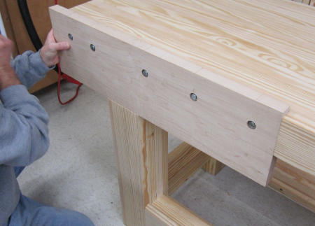
I laid out the spacing on the inner chop for the bolt hardware that will secure the chop to the end of the slab. Each hole had a counterbore large enough and deep enough to accomodate the washer and for a socket to fit nicely into the hole to turn the hex head.
|
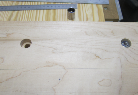 |
This is the dry fit. The two middle bolt holes were centered directly above where the main center screw will run.
|
 |
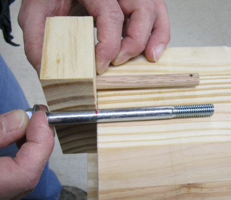
Following the instructions that came with the vise, we made a jig that easily allowed us to line lay out the bore holes that would match up with the hardware bolt holes. The jig had a 3/8 dowel that would slip into the bolt hole, the second dowel had a hole in it that allowed you to line it up underneath the slab and then tap a scribe to mark the center of the bore hole.
|
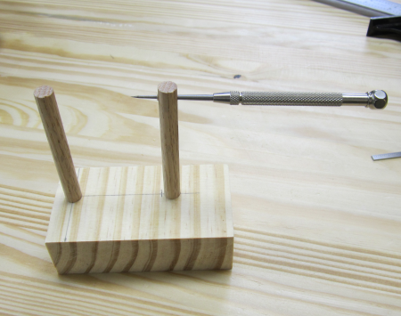 |
Example of the jig placement.
The scribe will mark the spot. |
 |
This image shows how the scribe
point will center a hole that will match up with the threaded section
of the bolt. |
 |
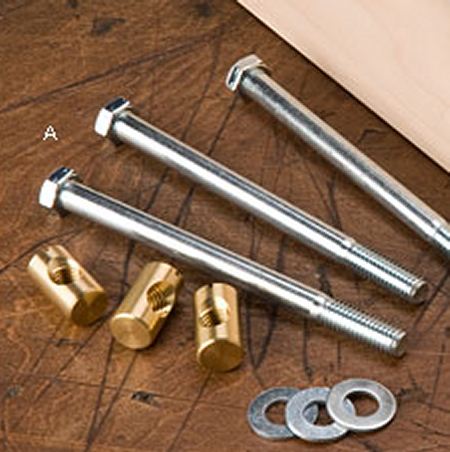
This type of hardware is normally used to connect bed frames and thus they are called bed bolts. The brass nuts will slip down into the hole and allow the threaded bolt to be secured. |
 |
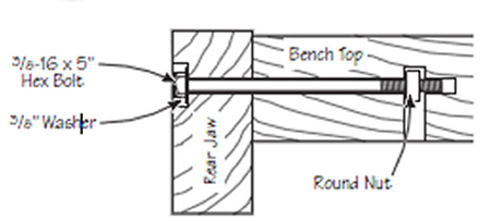
This diagram shows how the bed
bolt and washer work. |
 |
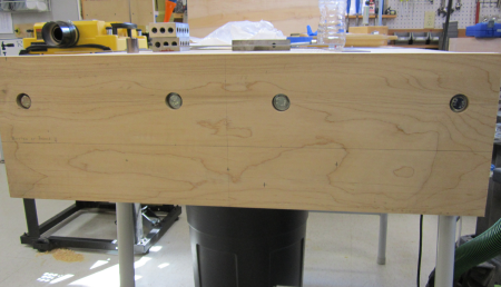
After the bolt holes were completed it was time to drill the vise hardware holes in the chops. The inner job and the outer jaw were sandwiched together for the cutting of all the holes...this included a 1.5 inch for the center screw, two 1 inch holes for the outer guide rods, and a .75 inch for the quick release mechanism.
|
 |
After the holes were milled, the inner chop was bolted and glued onto the end of the slab, completing the bread board end. Then a template was placed on the bottom side of the slab and holes for the lag bolts were laid out.
|
 |
Two of the holes were for 5/16
lag bolts and two of the holes had counterbores to accept 5/8 inch bushings. |
 |
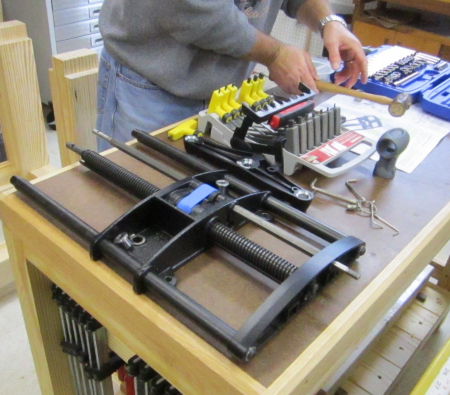
The vise had to be partially
disassembled so that the rods could be set through the holes in the
jaw chops. |
 |
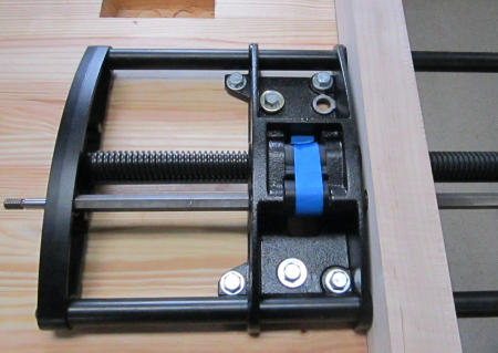
Here is the assembly with shafts
through the chop and the unit bolted onto the underside of the slab... |
 |
Then the outer jaw chop is added...there
were some issues with binding and adjustments had to be made to make
the screw and the guides work easily. |
 |
After the end vise was securely attached, the maple edges were planed. All of the chop dimensions had been slightly oversized and were then planed to exact joints. |
 |
Here is the slab top with the
end vise installed. |
 |
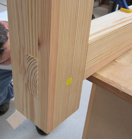
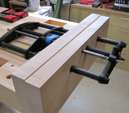
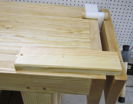
The first object held in the end vise is the inner chop that will be part of the front twin screw vise system. It will be longer and taller than the end chops. |
 |
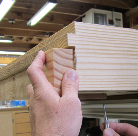
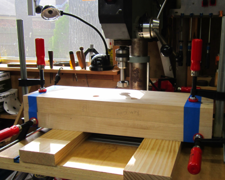
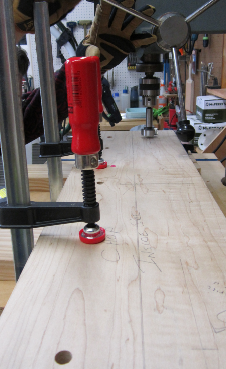
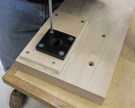
To prep the large inner chop...five counterbores and through drilled holes were put in a plane that would drill into the midway point of the side of the top slab. The chop was clamped to the spot and the through bore holes were marked by tapping the bit. |
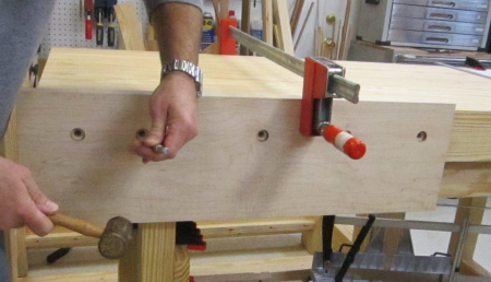 |
Then the holes were bored into
the slab. |
 |
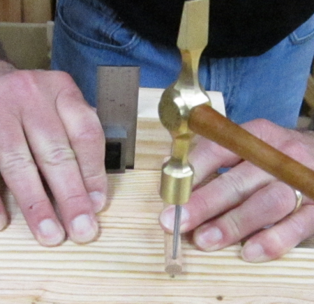
Then another jig was constructed to mark the centers for the cross holes. With the jig dowel in the bolt hole and the jig base squared to the side of the bench, a scribe was placed into the hole in upper dowel and tapped to mark the spot. |
 |
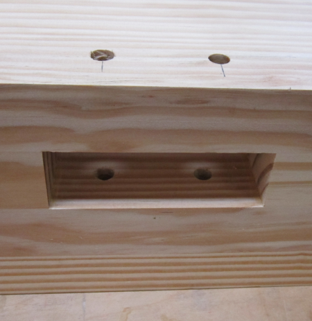
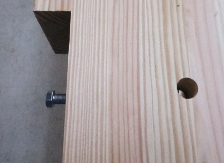
Example of the brass nut installed
into the cross bored hole for the bed bolt. |
 |
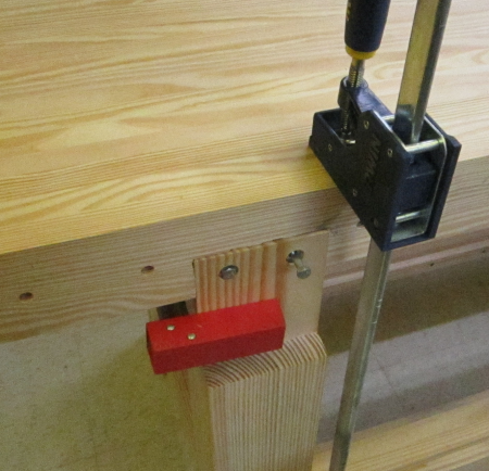
The next prep work on the bottom of the slab was to put holes into the left front leg tenon for two lag bolts that will connect the tenon to the back wall of the mortise. This is the "open sided mortise" that will be behind the vise jaw. The first thing to do was to counterbore and then drill the holes for the hex heads and washers of the lag bolts.
|
 |
Then we placed a template (1/4
inch piece of Luan) so that we could mark the holes. This was done by
placing the bit into the drilled hole and tapping the point to mark
the template. |
 |
This template was then flipped
over and clamped on to the back wall of the mortise to make sure the
pilot holes were accurately placed. |
 |
The eccentric head of the Festool
drill allowed the hole to be drilled into a tight corner. |
 |
Then a 5/8 wide, 1 inch deep
groove was routed to later accomodate the top edge of the Sliding Deadman. |
 |
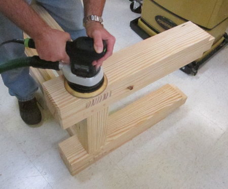
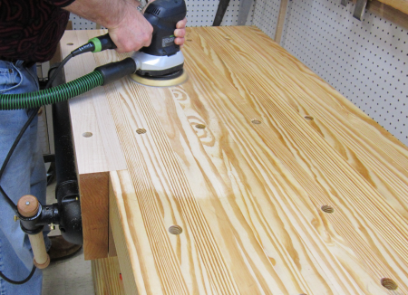
Final prep before the mating
of the top and bottom was to sand some areas that were easier to get
to with the base on its side. |
 |
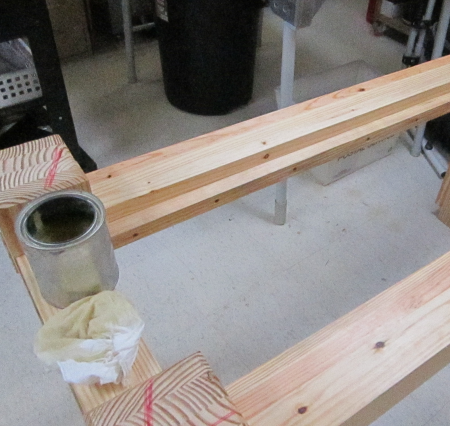
And a quick touch of the BLT
rub on the underside of the base. This area will be too difficult to
get to later. |
 |
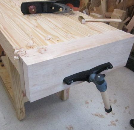
The top was then hoisted...and man had it gotten heavy...onto the base. The four mortises were pounded down onto the tenons. There was a good mating on all of the outside shoulders. The tenon for the open mortise was lagged down tight. This made everything fit well and the outer surfaces were co-planar. |
 |
Clamps were run from the stetchers to the top slab for the glue-up. At this point the workbench really became a reality. The bench was born...and the all important mantra was uttered..."it ain't going nowhere..." |
 |
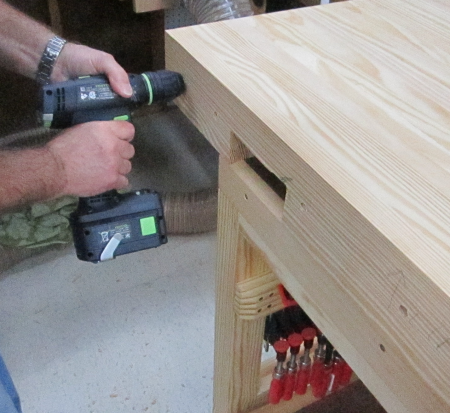
After glue set, 1/2 inch holes
were bored 5+ inches through the tenons for oak dowel pins. This will
help maintain joint stability after years of racking forces. |
 |
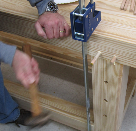
Dowels were glued and pounded
into the holes. |
 |
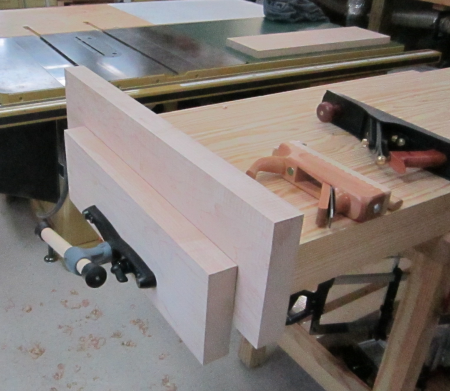
Then the inner chop of the twin
screw vise was dry fitted. Edges were marked and then milled down to
final tolerances. |
 |
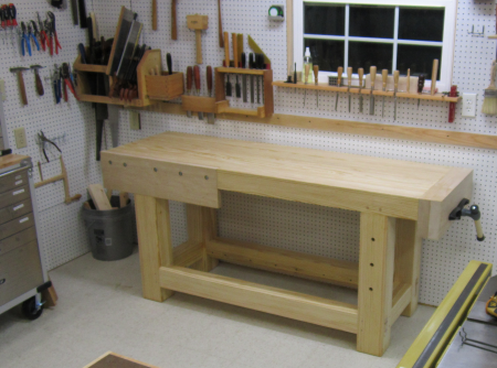
We moved the bench from the
construction area to its final resting place. All remaining work can
be done here. |
 |
The bench will live under the
south facing window that was recently installed to give natural light
to this work area. |
 |
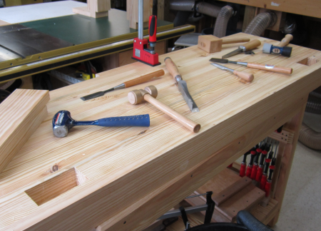
All hand tools that will be
used on the new benchtop will be close at hand. |
 |
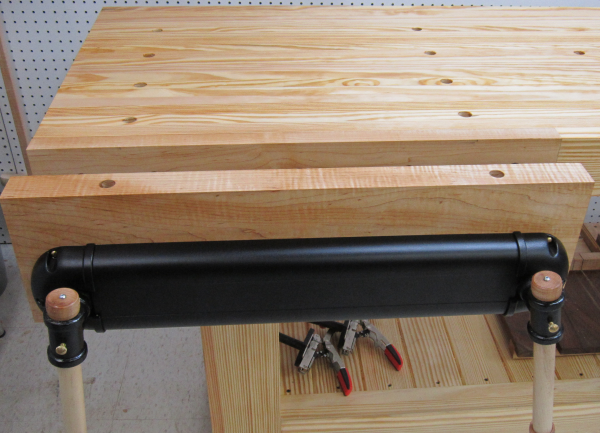
Further work on the twin vise
chops...1.5 inch holes for the twin screws were bored. |
 |
Spacers were added to the back of the inner chop to provide for the proper thickness to accomodate the hardware. The screw assemblies were installed. |
 |
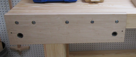
View of the front of the inner chop with hardware installed for a dry fit. A little work remains on the outer chop and then the large front vise will be completed. |
 |
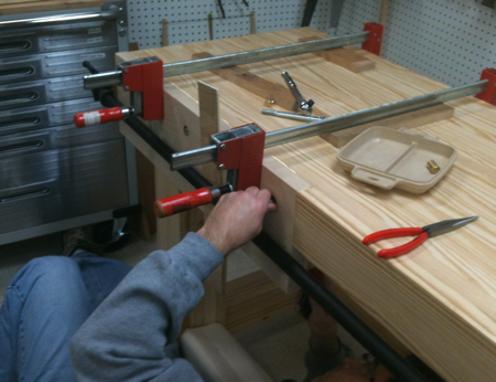
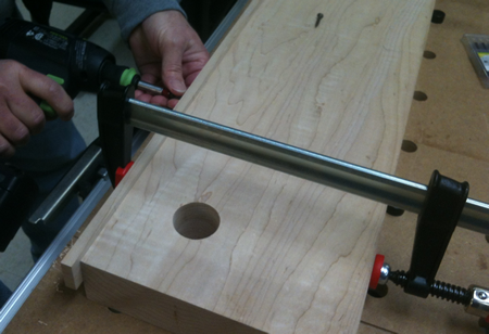
Here the rear twin screw chop
is being glued and bolted to the top. |
 |
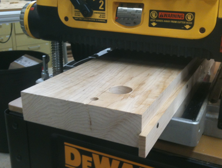
One of the things that we wanted to do to the outer jaw was to bevel the inside face of the jaw so that when tightened the chops would grab at the top first, rather than lower in the jaws. We had read of a way to bevel the inside that involved glueing a strip on the front of the vise and then running it through the planer at an angle. We did not like the idea of making the front of the vise jaw ugly...so we screwed a temporary board to the side of the jaw that was 1/4 inch proud along the run. |
 |
Then we put the jaw into the planer with the elevated strip facing down. We then ran the unit through the planer five passes and thus put a bevel that dropped the inner bottom of the jaw 1/4 inch over its 8+ inch run. |
 |
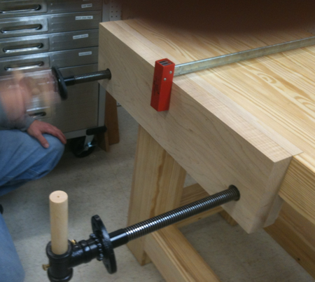
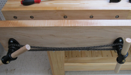
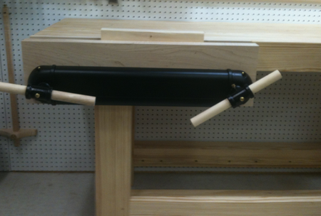
After finishing the milling on the outer jaw it was time to install the two screws into the threaded receivers that were previously installed on 24 inch centers. Once they were in we drilled the holes to attach them to the outer jaw. Then a chain was installed to run from one screw to the other. |
 |
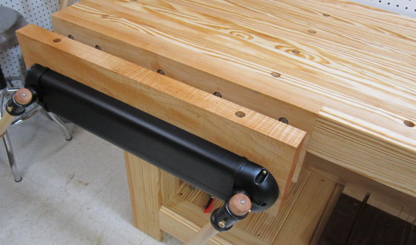
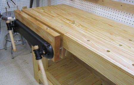
Here are the twin screws with
the chain drive installed. |
 |
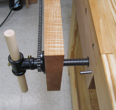
Here is a side view of the chain
mechanism, the outer chop, one of the screws (with its protective pin
installed, and the inner chop which is co-planar with the bench top. |
 |
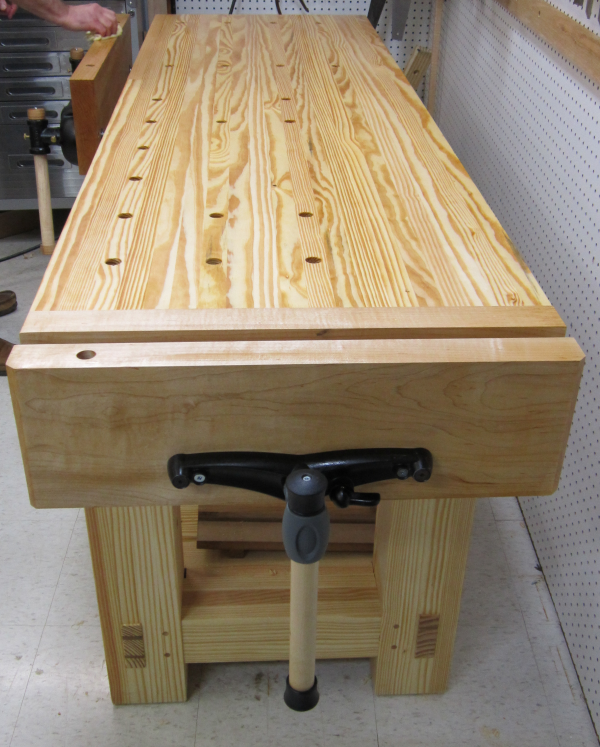
After the chain cover was installed
we gave it the first test...performed well...now to tune up the unit,
put in handle ends and stops, etc. |
 |
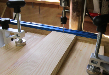
Next phase was to put in the lower shelf. Twelve boards were milled to a width of 4 1/8 inches and a thickness of 1 1/4. Top edges were chamfered. The final prep was to drill a hole at both ends of the board. The centered hole was drilled along with a counter bore for square drive screws. A jig was set up on the drill press and this helped make quick work of the 24 holes. Then all surfaces were coated with a BLT rub and installed. |
 |
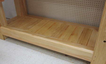
The boards were screwed down to the ledger boards that were installed on the inner edge of the long stretchers and the surfaces of the boards sit about 1/8 inch below the stretchers. The two end boards were trimmed to install tightly around the legs. Here is the finished product. |
 |
After the success we had with the interior face bevel trick on the big vise I realised that I wanted the end vise to be bevelled. I pulled the end vise outer jaw and did the same bevel trick on the inner face of that chop. Then I put a chamfer on the two outer edges of the outer face to ease the edge. I did this on the table saw. All surfaces were sanded one last time and then had a coat of linseed oil spread and the unit was reinstalled. |
 |
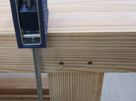
After reinstalling the end chop, I tested the front edge bench dog system. The holes in the bench were drilled all the way through the top. A long brass dog is used in these holes and that dog can be set below the bench surface for storage. A hole was drilled in the chop that accepts a short brass dog which will always be out proud of the top edge of the chop. It may be removed. |
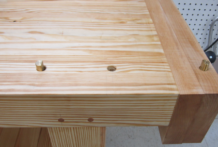 |
Here is a view of the dog set up.
The accessory at the top of the image is a Veritas vise rack stop. Polyethylene shims are used to keep the vise jaw parallel to the top and thus stop the chop from racking. |
 |
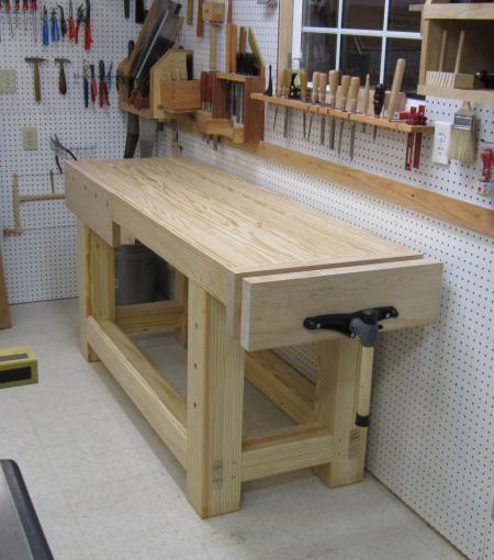
The end vise is now completed
and the unit is totally functional. |
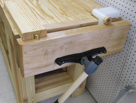 |
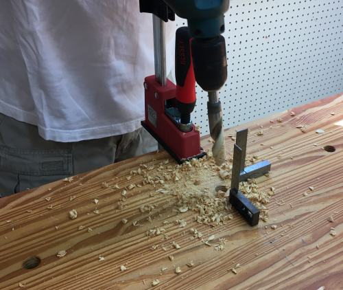
Some dog holes were spaced into the interior of the table for holdowns. Due to the proximity of vise screws and metal plates under the bench, the through holes were finished off with a manual brace and and bit. |
 |
A second dog hole jig was created
to put the rows that extended from the twin screw vise. |
 |
Some final sanding and BLT rub. |
 |
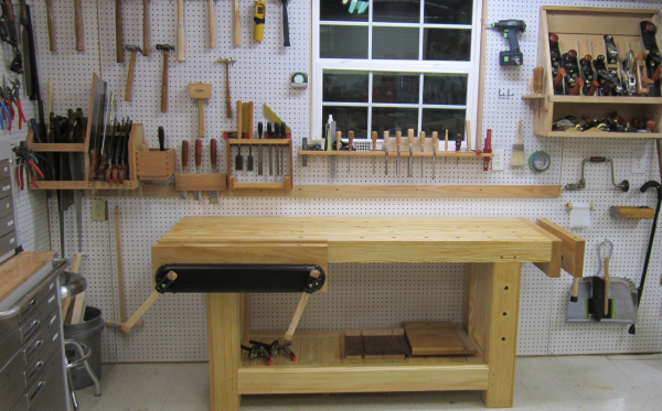
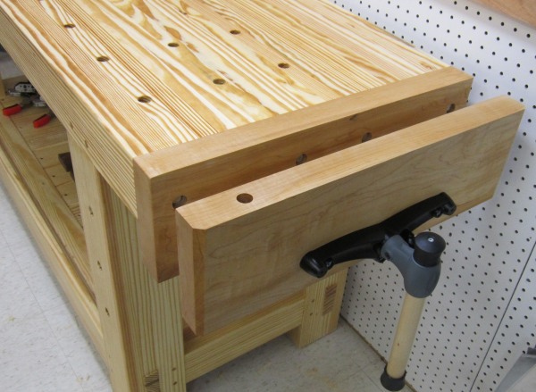
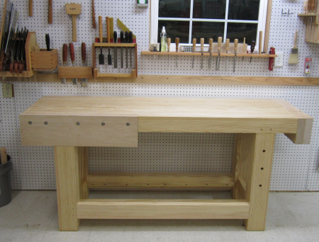
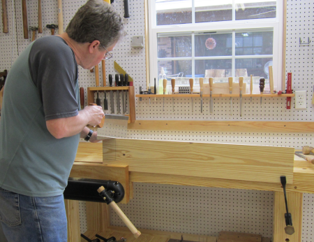
The final product is ready for service. A few cosmetic planing, sanding and oiling sessions remain and a Sliding Deadman option remains a possible future addition, but the workbench is 100% ready for duty. |
 |
The first use... |
 |
Later modifications... |
|
Added more dog holes in top...used new lipped 3/4 HSS bit from Veritas...so much easier to do than the first ones... |
 |
Added a Benchcrafted planing stop... |
|