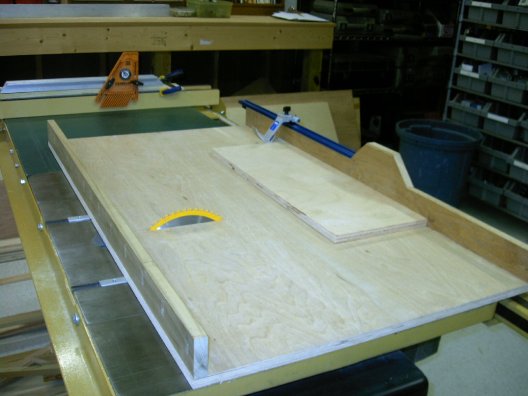
I had given up on an old, overweight crosscut sled when I started using the Festool to cut large panel goods in the garage. Crosscuts on smaller materials were being made on the MFT3 table...but a recent project, making 6 slantboards, made me desire better production capabilities for medium size crosscuts. So I invested in a new Incra 1000 mitre gauge for angle cuts and planned a new crosscut sled for square cuts. I had seen some designs by William Ng and Marc Adams online. I planned something of a hybrid between the two designs and we made sure that we had a grasp of Ng's formula for his 5 cut squaring method. Here is the model that I had eliminated a couple of years ago.
|
|
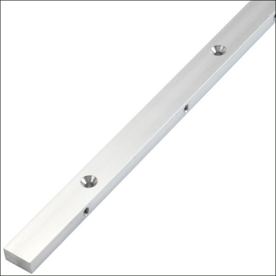
We started with two 30 inch aluminum runners that were hold overs from the first sled. The runners had adustable nylon set screws along the length of bar to reduce slop in the miter slot.
|
 |
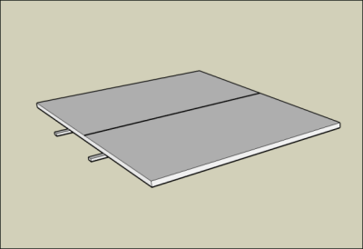
| The runners would be attached to a 28 x 38 base of 3/4 inch Baltic birch. The base is roughly the size of the cast iron top of the Powermatic 66. |
 |
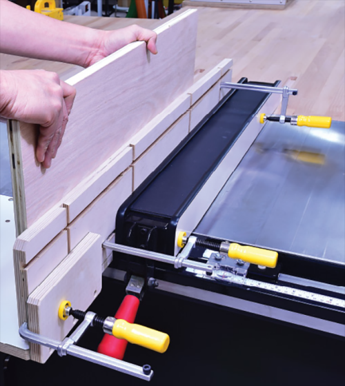
| The fences for the sled were glued up with 5 layers...two 3/4 inch Birch ply on the bottom, then two 3/4 inch MDF with a final 3/4 inch Birch on top. | 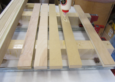 |
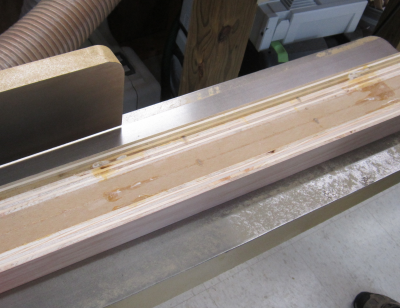
| Here are the fences after glue-up. | 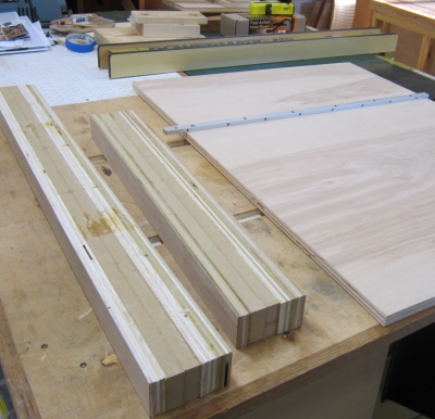 |
The fences were quite rough so they went to the jointer...bottom and faces were squared. James and I had some difficulties during the fence calibration and we ended up having to square the face again. |
 |
| The runners were screwed on the bottom of the sled. | 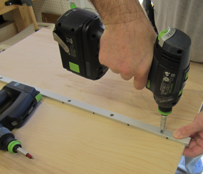 |
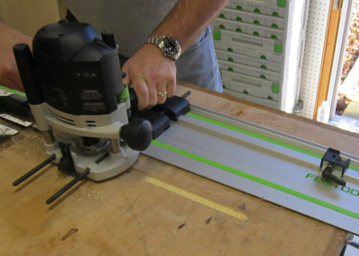
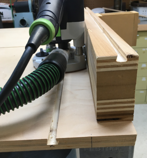
The runners on the new unit would need longer dados in the outfeed table to enable the sled to carry past the blade. The Festool fence and router setup allowed this to be done quite precisely. It also allowed for easy dust colleciton. |
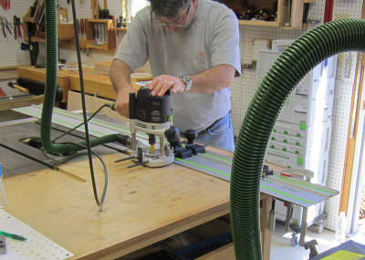 |
The grooves were extended so that the sled would carry the perfect distance past the blade. Here the stop in the right corner established the end point of the dado. |
 |
| The new grooves. | 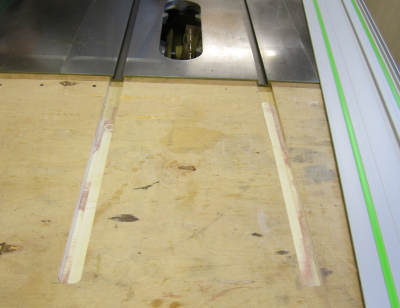 |
| Once the fence was finally calibrated, many screws were sunk throuth the bottom of the base into the fence to hold that angle. | 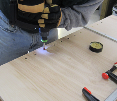 |
| The second slide was installed and the nylon set screws were adjusted to eliminate play in the mitre grooves. | 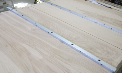 |
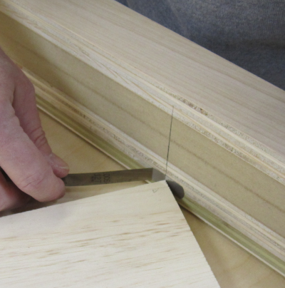
Calibration process... During the initial squaring process a thin board needed to
precisely fit in the kerf that had been cut in the base. To get a precise fit a thin strip was planed.
|
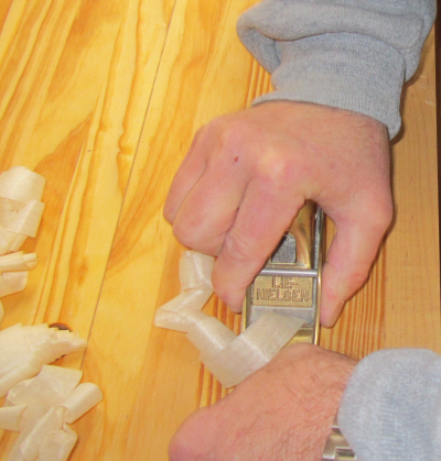 |
| LN 102 bronze block plane... | 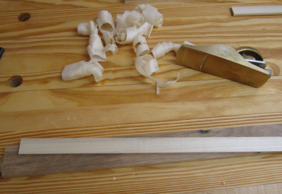 |
| Test fit in kerf... | 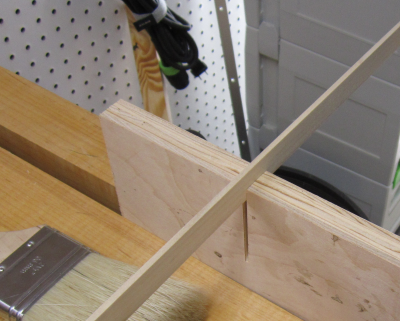 |
| Strip in the kerf in the base of sled... | 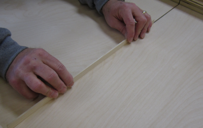 |
| Then square was secured against that strip in the kerf as the reference leg of the square. | 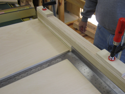 |
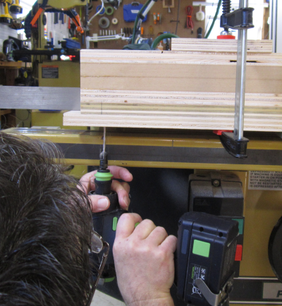
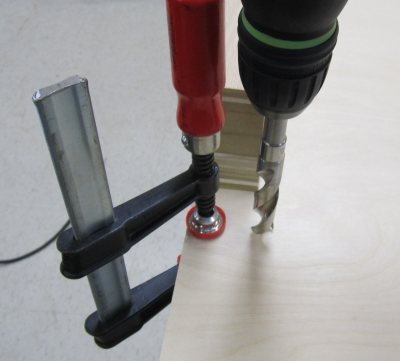
A screw at the right end of the fence was used to secure the unit to the base at the established pivot point (two inches in from the right end of the fence). Then the left end gets a screw at the 30 inch measuring point. This screw is located at the adjustment point for the fence. Image shows the "adjustment" screw location being drilled and counter sunk. |
 |
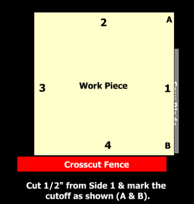
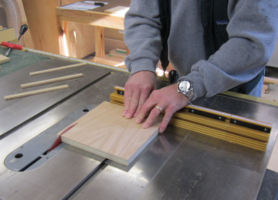
After squaring the fence it was time to run the 5 cut test using William Ng's formula. The process starts by marking the long edge of a rectangular board. Then the first cut trims that edge and after an edge is cut it then goes against the fence. This is done four times. On the fifth cut you are now back where you started. This fifth cut produce the cut-off that is used to determine squareness. The cutoff is marked A and B as shown in the image.. Ng's formula: A – B ÷ 4 ÷ L x P = E A = width of cut-off at far end; B = width of cut-off at near
end; E= error per inch to adjust |
 |
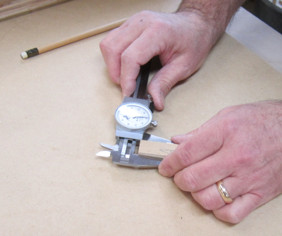
Precise measurements for A and B are determined by the caliper. D, the difference between A and B widths, is then calculated to thousandths of an inch. If D is a negative number then the left end of the fence needs to be pushed forward in the amount of E. If D is a positive number then the fence needs to be pulled
backward in the amount of E. Ng has a video that explains this process at: wnwoodworkingschool.com/5-cuts-to-a-perfect-cross-cut-sled/
|
 |
The adjustment being made here is .005 inches...it is being made at the P = 30 inch pivot mark. If the fence is "high" and must be pulled away then the marking board is clamped down to mark the point, the fence pivot screw is removed, the fence is pulled away and then is put back with .005 inch feeler gauge in place. Then a new screw is put in place. If the fence is "low" and must be pushed toward the table, then the marker board and the feeler gauge are clamped to the table, the fence pivot screw is removed, the feeler gauge is removed, the fence is pushed to contact the board. Then a new screw is put in place.
|
 |
| After some trials and tribulations we finally got the finished product that produced square cuts. | 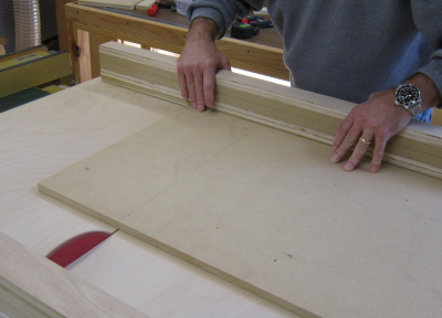 |
| Final touch to promote safety was to make a box out of MDF. | 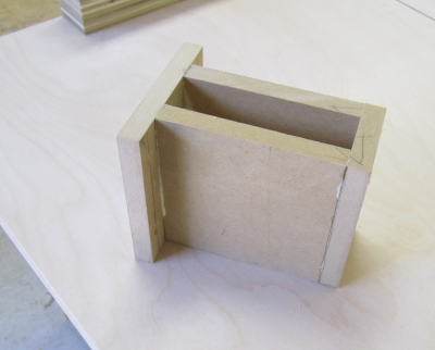 |
| This was attached to the rear of the sled to cover the blade when it emerged from the fence. | 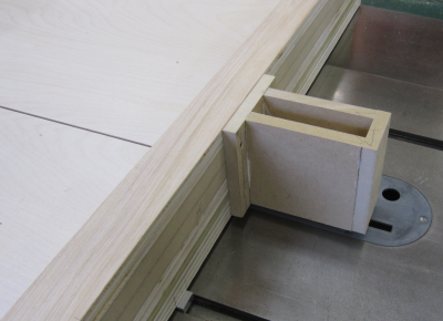 |
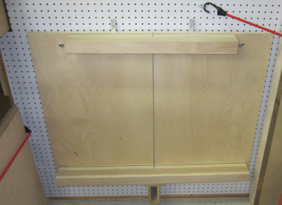
After testing the unit, I drilled
a couple of holes is the front edge to allow the unit to be hung for
storage. |
 |
The sled hangs on pegboard in
the northeast corner behind the storage spot for the router table. |
 |
After using the Ng method to
square the crosscut sled we used the same principles to square the fence
on the new Incra 1000 miter gauge. |
 |
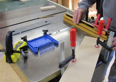
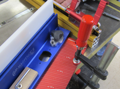
There was the added difficulty of keeping the gauge steady. Here we used a Kreg mitre slot featherboard to stop the mitre gauge bar in the slot. That was backed up by the GripTite magnet featherboard. We had some difficulty securing the pointer board properly to achieve the measurement against the Incra fence. |
 |
To hold down the reference point more securely we took an aluminum Woodpecker angle measuremnt plate and put a corner on the reference mark. In addition to a clamp, the Carter MagFence was used to prevent any movement. This worked much better that a wooden reference point. Final meaurements were successful and the Incra fence was locked down square. |
 |
MatchFit Alterations and Jigs |
|
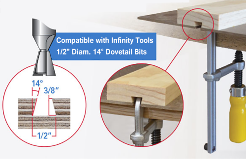
I purchased some MatchFit clamps, a dovetail bit, and accessories...these enabled me to route grooves and make some appliances...manufacturer's examples to the right... |
 |
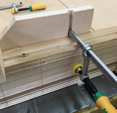
On the crosscut sled...I routed
through grooves that are parallel to the fence...had to make sure they
were not in line with the screws to the mitre bars. |
 |
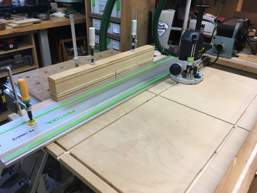
Used the Festool guide to create some grooves parallel to the front edge and to the back fence. |
 |
The routed dovetail groove is mated with a dovetail clamp. |
 |
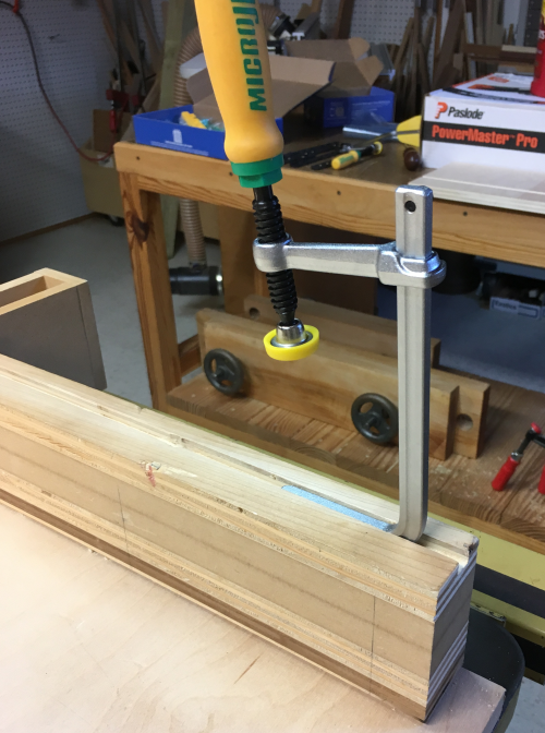
Routed a groove in the top of the fence. MatchFit clamps will run anywhere in this groove... |
 |
Example...holding a block stop... |
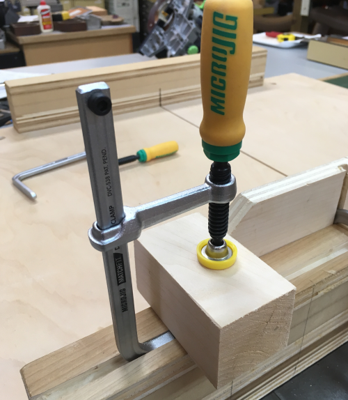 |
Jigs with grooves routed into
them can be clamped to the fence on the outside... |
 |
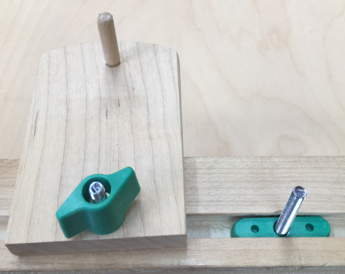
Custom jigs, appliances, and stops can be placed anywhere along the fence using knobs from MatchFit. |
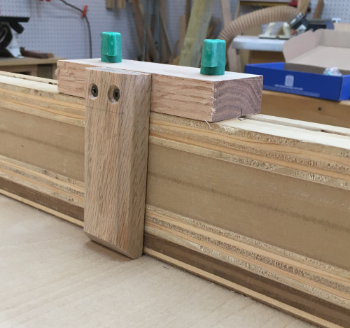 |
Dovetail shaped plates with bolts run in the groove...handles tighen.
|
 |