|
Arch for Wedding of Sarah and Daniel |
|
| Typical arch configuration...Sarah wants something like this in a dark wood. | 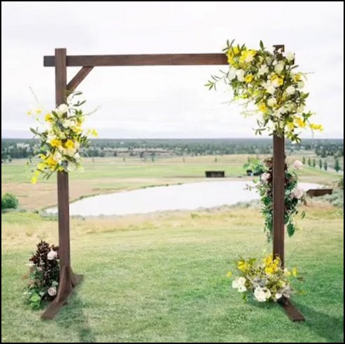 |
|
|
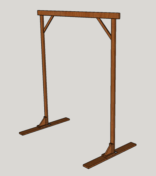 |
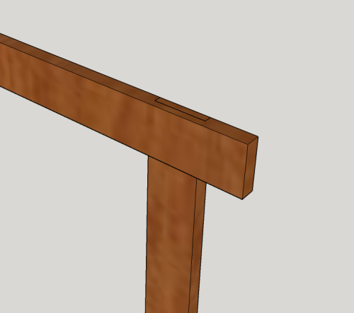
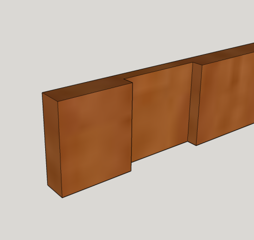
| Joint of crosspiece and
leg...front view. Crosspiece = ~85 inches long This means that the interior opening between the legs is 6 feet. The leg height is ~95 inches long, allowing for the distance from the bottom edge of the crosspiece to the floor is ~91.75 inches (providing about a foot of clearance from the top of the minister's head) The distance from the the top of the arch to the floor is ~95.25 inches. |
 |
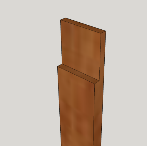
| Front view of leg...this rabbet
cut will provide a cheek about 1/4 inch with ~1/2 inch
shoulder...this will match with the dado in the cross piece to
create a T-lap joint. |
 |
| The backside of the crosspiece
will have a dado... |
 |
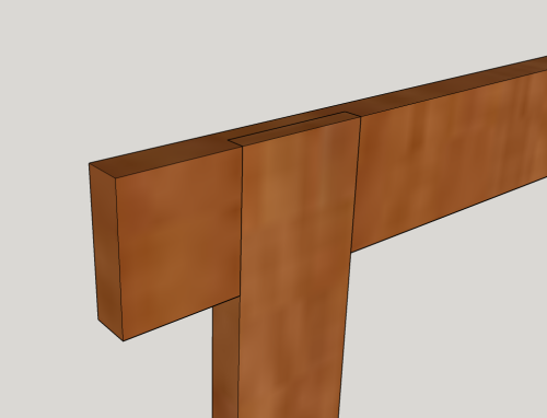
| Rear view of crosspiece and leg
joined in a T-lap joint. |
 |
|
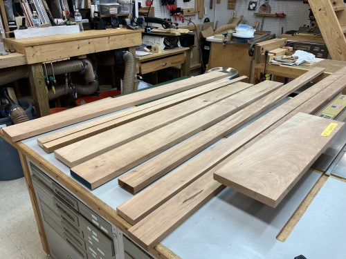
I had a number of boards of cherry...all 5/4 thick by various widths. Should be able to joint and plane to four square at
around one inch thick. |
 |
| Cut list...plus hardware needs, materials | 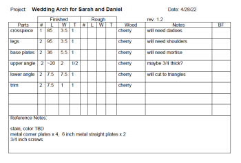 |
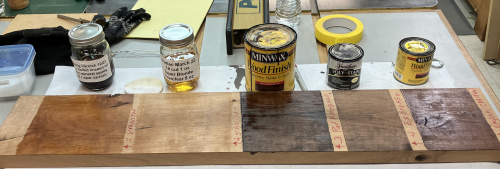
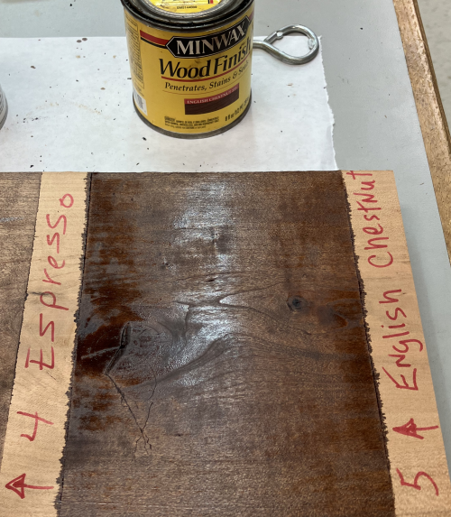
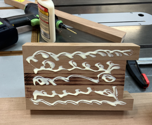
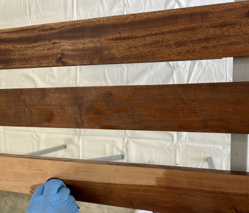
| Color test... had no cherry stain on hand, wood was planed, but not sanded, two coats, rubbed on |
 |
|
Color chosen...#5 Minwax stain, English Chestnut |
 |
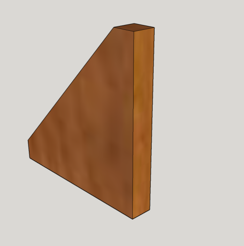
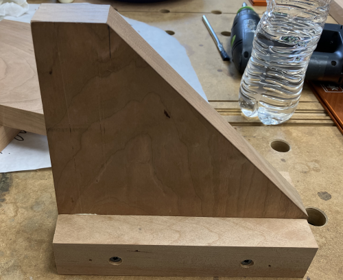
| The front face of the base
assembly will have the wooden support angle already secured with
glue and screws. The angle assembly starts with a 7.25 x 7.25 inch square that is then cut at 45° at the one inch marks. |
 |
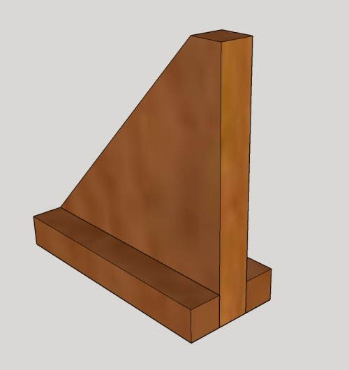
| Two horizontal support trim
pieces (1 x 1 x 7.25) are then glued and screwed to the angle
board. |
 |
| Two vertical support trim pieces (1 x 1 x 6.25) are then brad nailed and glued to the angle board. | 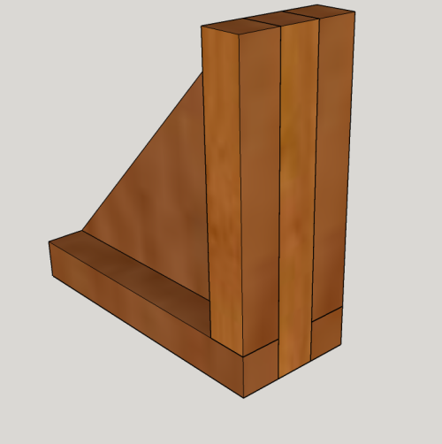 |
| Two longer horizontal support
trim pieces (1 x 1 x ~8) are then glued and screwed to the angle
board. These will protect outer edges of the vertical leg. |
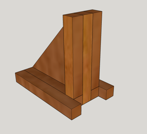 |
| The angle assembly will then be
glued and screwed into position...it will form a pocket for the
insertion of the leg into the mortise. Length of base is 48 inches, width is 5 inches, height off floor for the base is one inch, height off floor of the angle assembly is ~8.5 inches. There is a mortise that is ~7/8 inch x 3 inches and is 3/4 inch deep. It will be placed in the center of the base board. |
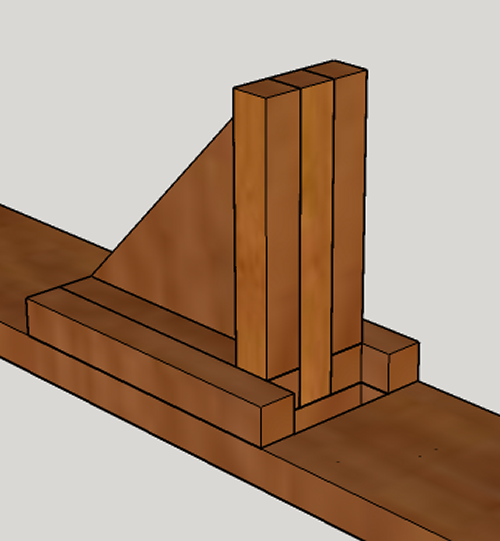 |
| Image shows how the leg will fit
into wooden supports...wood screws will connect leg and
assembly. |
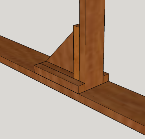 |
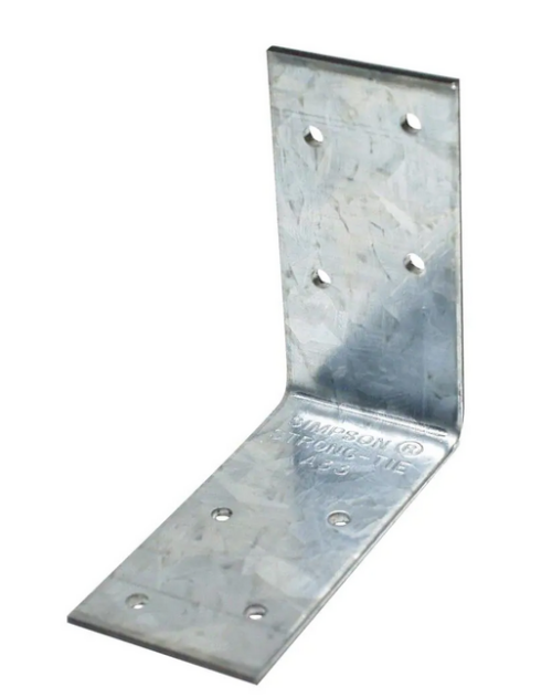
| Metal bracket will be secured
with screws...3/4 inch screws into the base, 1.5 inch screws
into the angle assembly. |
 |
| Need four of these inner corner
braces (Orange BORG)...will be attached with 3/4
inch screws... |
 |
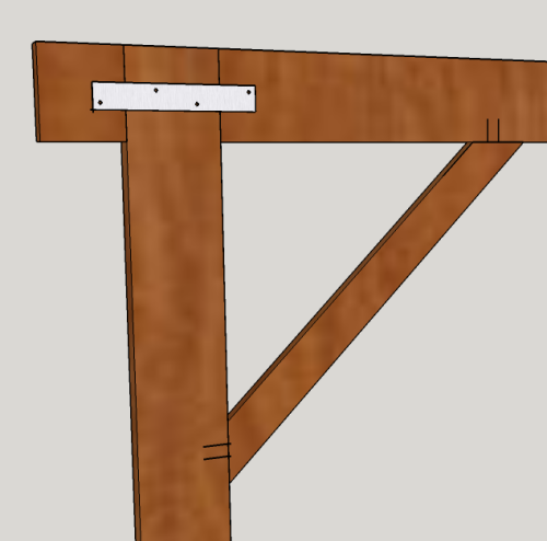
| The crosspiece connects with the
top of the leg at a lap joint. On the back side of the crosspiece, they will be connected with a metal plate, 6 inches x 1.12 inches... The 1/2 inch angle supports will be coplanar at the backside of the leg and the crosspiece. They will be connected via screws in Kreg pocket screw holes...locations shown by parallel marks. |
 |
| Need two of these plates (Orange BORG)...will be secured with 3/4 inch screws. | 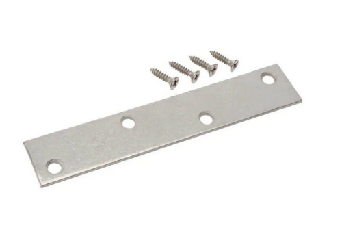 |
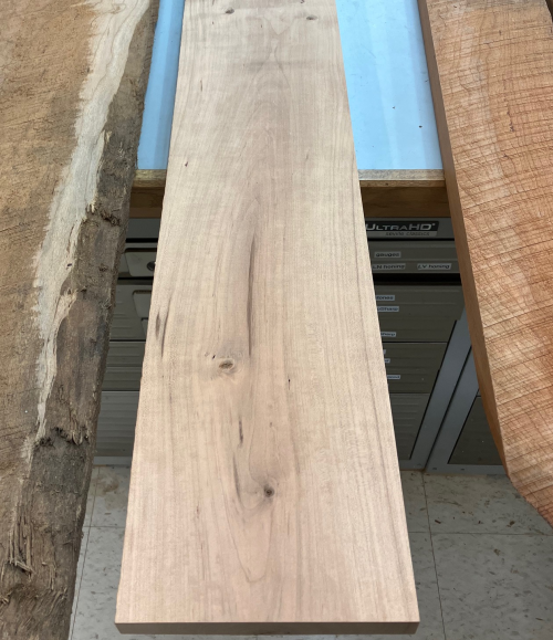
| The rough cherry blanks were a
variety 5, 6, or 7 inch wide boards and were 6,
7, or 8 feet long...they will need to be milled 4square...they
are all at 5/4 rough, will plane to one inch. |
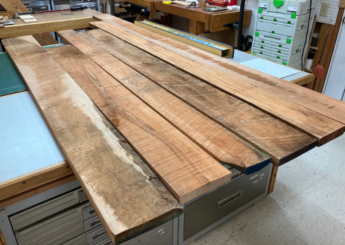 |
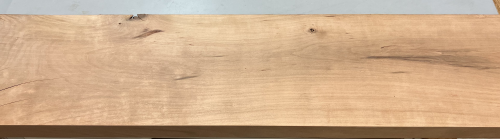
| This is a typical board after a
face is surfaced... |
 |
| Blanks will be jointed on a face
and edge at the jointer for 2square |
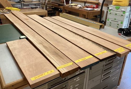 |
| Then surfaced at the planer and
ripped at the table saw for 4 square. |
 |
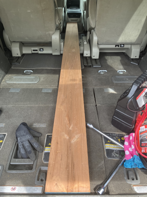
| Test fit...longest boards are the
legs...96 inches. Perfect fit in the van. |
 |
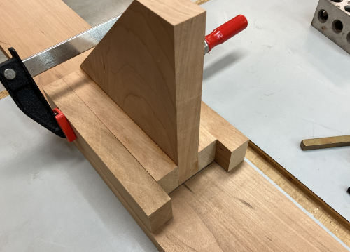
| Making the angled leg supports...cut the 45 degree on MFT3 with new guide system. | 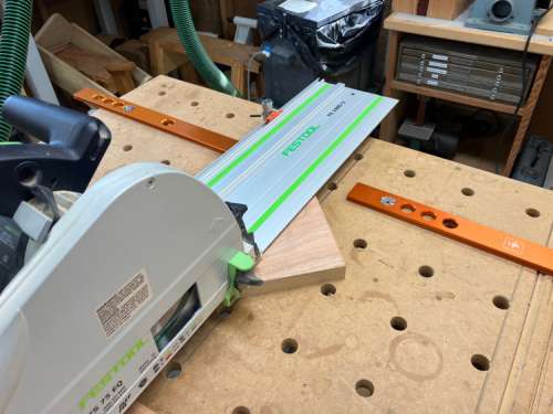 |
| Dry fit mock up...the 1-2-3 block shows the location of the three inch wide leg. | 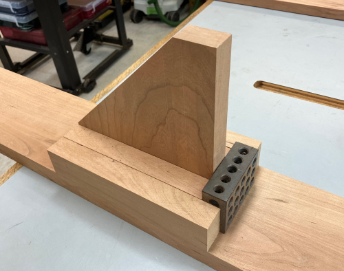 |
| The base board will have a mortise in the three inch opening shown... | 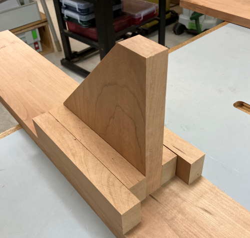 |
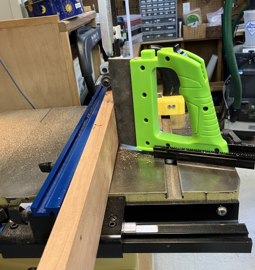
| The hardest joinery was out at
the ends of long boards...the crosspiece is around 7 feed long
and there are two dadoes about 3.5 inches in from the end and
extending another three inches. These dadoes were milled
at the P66 using the 1/4 inch Infinity blade, Using a sled to hold the material in place, the hardest part was the outrigger...we used a support board the thickness of the sled and Cindy worked the outrigger quite well. |
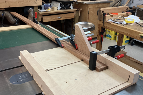 |
When attempting to use the same setup for the rebates on the ends of the legs, there was a problem with getting the P66 blade trunion assembly to fully lock. So, went another direction on the rebates...made the three inch cheek cut at the bandsaw...used assist to hold the wood against fence and had a mag stop at the three inch mark to prevent over cut. Cindy had the eight foot outrigger behind me. |
 |
| I hand sawed (small Bad Axe tenon) the shoulder cuts... | 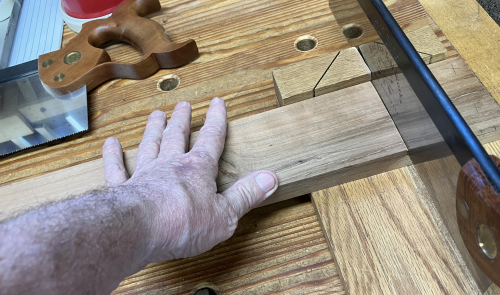 |
| Cleaned up the shoulder with LN small tenon plane. | 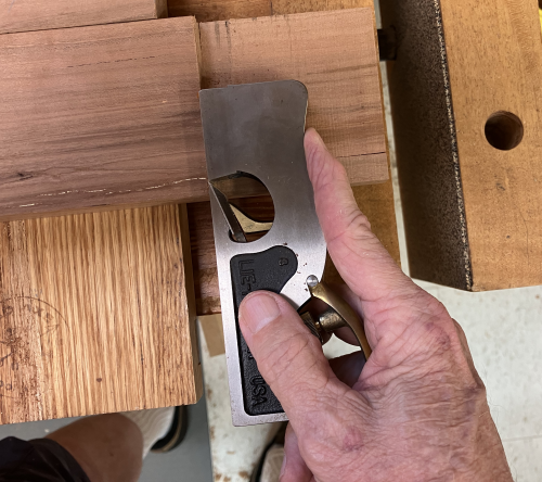 |
|
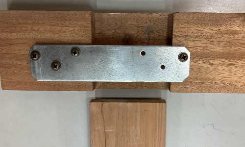
The crosspiece and leg joints
are held in place with a support plate.
Centered holes were drilled
using a VIX bit.
|
 |
|
The original design had to be
changed due to a different plate secured at the BORG.
This is the rear view of the right joint. The three outer holes screw into the cross piece and they received #8 round head x 3/4 inch screws. The inner single hole on the
right also got a 3/4 inch screw.
The plate as shown in the image stays attached to the crosspiece. |
 |
| To verify that the correct surfaces are being joined...match up the red dots...the surfaces with dots will face each other. | 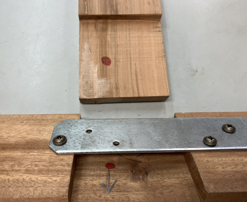 |
| Then slide leg under the plate into the dado space... | 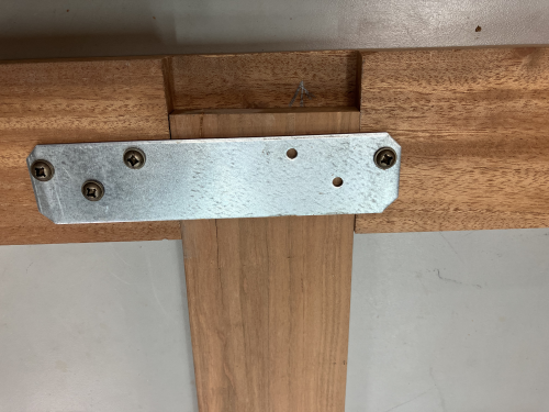 |
| The leg will slide into the dado
until the shoulder stops the slide... the two holes in the plate will accept two #8 round head x 5/8 inches. These are shorter because they only go into the check of the leg. |
 |
|
Creating the angle assembly
for the base-leg joint...a sandwich was created with the angle
plate in the center and with two short horizontal support trim
pieces...these were glued and screwed...
|
 |
| Another set of longer
horizontal trim pieces were attached via glue and brads. This created a pocket that will hold the leg...it also located the mortise. |
 |
| The five pieces, when glued together, had a bit of a wobble to them...ran the unit across the PM jointer. | 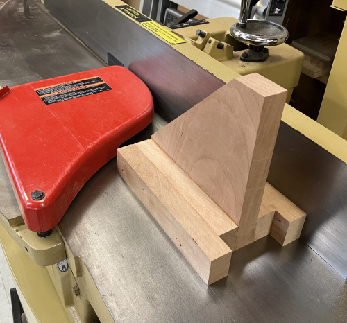 |
|
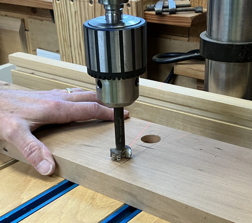
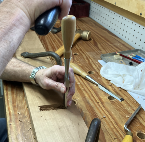
The mortise was laid
out...considered using the PM bench mortiser but indexing was
going to be problematic...in the middle of a four foot long
board.
We opted to hog out most of the mortise with a 7/8 inch Forstner bit. |
 |
| The balance was removed with
chisels. |
 |
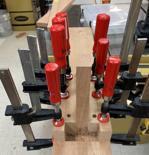
| To attach the angle
assembly...the unit was dry fit around the CTD leg. Then
glue was put over the bottom of the plate. |
 |
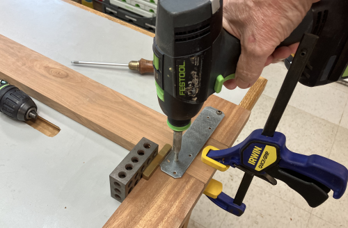
| Then two #8 x 2 screws were put
through the plate in pre-drilled holes...the counter sunk screw
heads will be covered later by the vertical trim. The assembly was then clamped. Image shown is after the CTD was removed from the pocket. |
 |
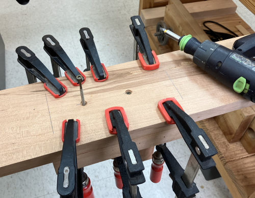
| While the glue was drying, screws
were put in from the underside of the base plate into the
assembly...two #8 x 2.5 screws into the center piece, #8 x 2
inch elsewhere. |
 |
| To create the joinery for the
upper corner supports...Kreg pocket joints were created on the
crosspiece and the legs. This was challenging due to length of material, 7-8 feet. |
 |
| Each 45° end will
connect with a Domino floating tenon which will act as the
indexing point...then a pocket screw will tighten the joint. Our two boards were of different thicknesses...I wanted a shadow line on the show side, coplanar at the back. So we indexed the Domino off the table surface with the two backside facing downward. |
 |
| The ends of the supports had to
be receive Domino at 45°. |
 |
| As elsewhere, the length of the
work piece caused the most problems. |
 |
 |
|
| To make the joint connection
easier, the upper support pieces are marked with red dots on the
45° end. One end of the support piece connects with a leg...shown here. The Domino tenons are glued into the support. The Domino tenon is not glued at the connection to leg. First step is to make the support - leg connection. |
 |
| The leg should be partially pushed into the dado-plate pocket...stopping at the dotted line. |  |
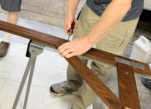
| After the two ends of the support
are in good contact, #8 x 1 inch screws are inserted into
the Kreg pocket and secured. Then two #8 x 5/8 screws secure the plate. |
 |
|
|
|
| Cornered and chamfered base plates ease the sharp edge...Sanded at 120x...unit then transported to Saltillo for test assembly and stain. | |
| Stain was applied...rubbed on. Top board is the mahogany piece that was hiding among the cherry boards. |
 |
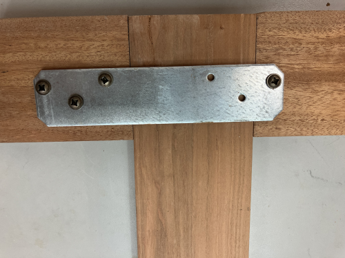
| Final test of the joints for the
the upper supports... |
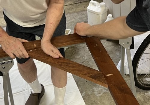 |
| Screws inserted in to Kreg joints
and into pocket plate. |
 |
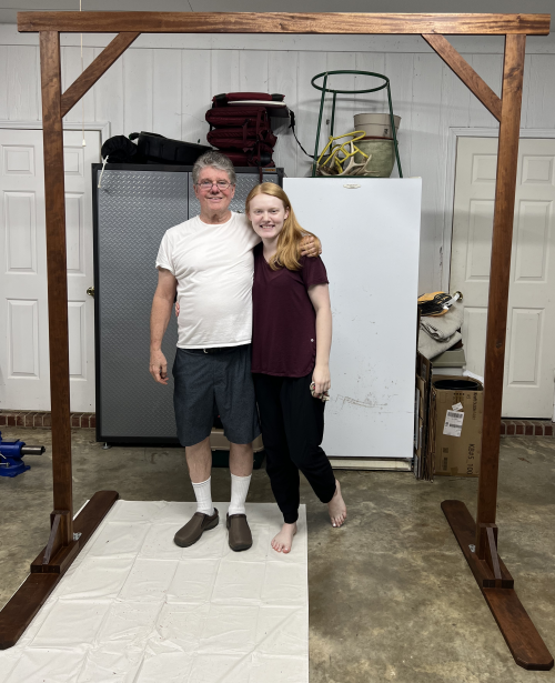
| The completed unit is raised for
the first time. |
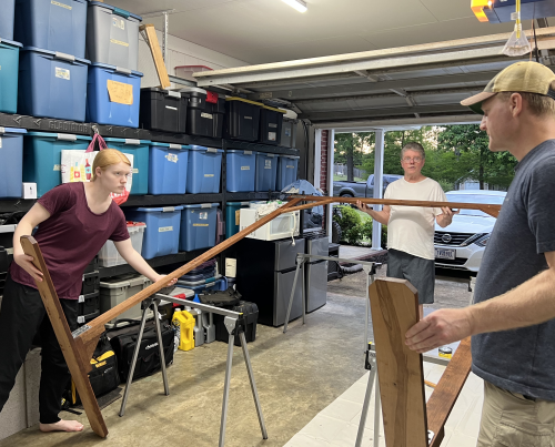 |
| With the bride to be... |
 |