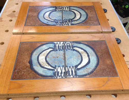
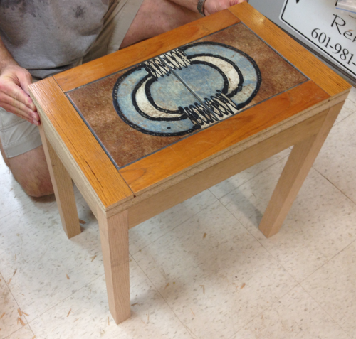
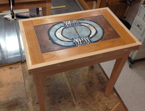
This project is for Cindy's sister, Pam. Their mother and father had owned an oak dining table with inlaid tiles. Pam had inherited the table after Aurelia's death. She used the table as a dining table until she recently decided that the table must be replaced. This image is one of the fold down leaves with a two-tiles inset. Cindy and I brought the two leaves home with us from N. Carolina. |
 |
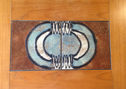
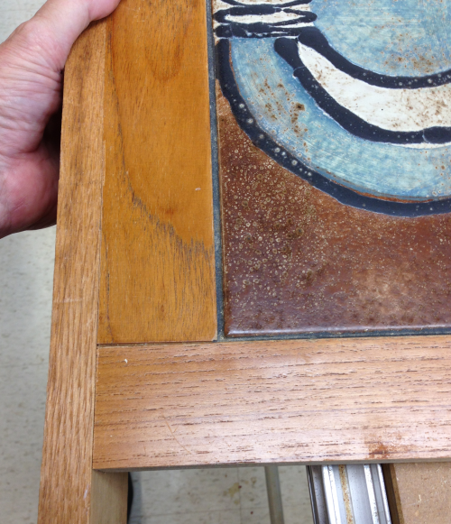
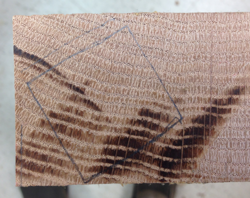
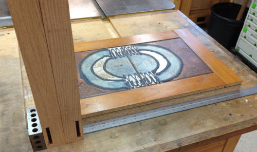
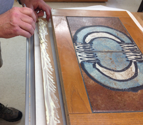
Pam wanted some ideas for how she might keep the tiles and repurpose them. I thought that the tiles might be inlaid in a pair of side tables. Here is a close up of the tile. The wood is some type of composite with oak veneer. |
 |
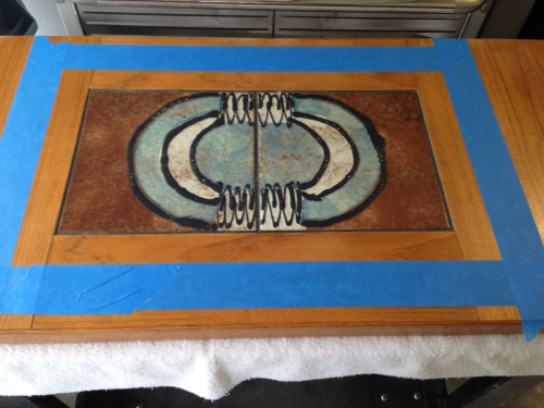
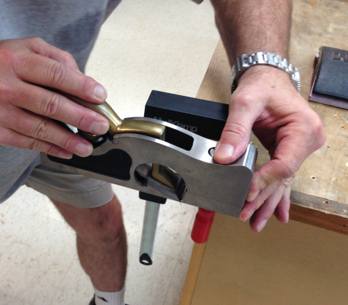
As we threw around some ideas for how to "remove" the tiles, James proposed that we cut out the tile and keep some of the material around it...then we would just create an oak apron and legs. Here some painters tape was put in place to get a sense of proportions.
|
 |
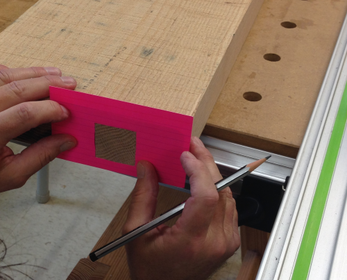
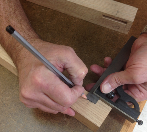
I settled on a two inch border...knowing that I could always trim more off...I marked off the edge and scribed it with a knife. |
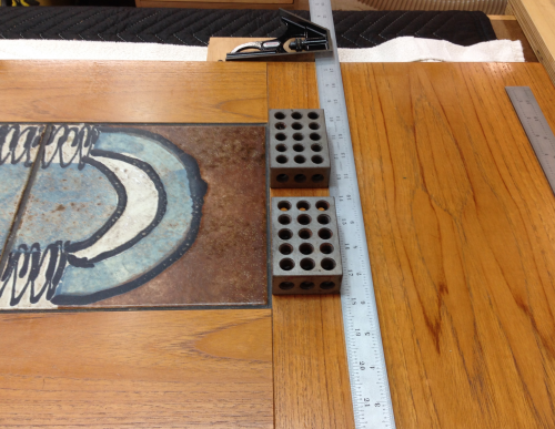 |
On the short side I measured the two inches...marked that with a knife... |
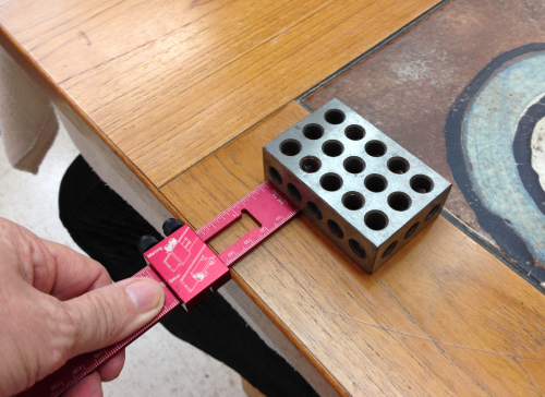 |
...and set a marking guage to that and scribed the lines. |
 |
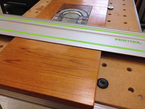
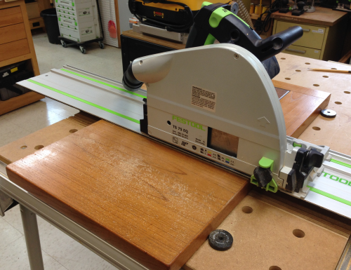
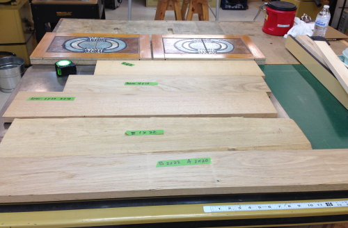
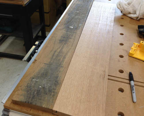
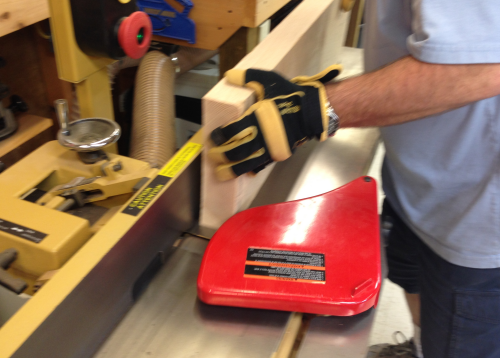
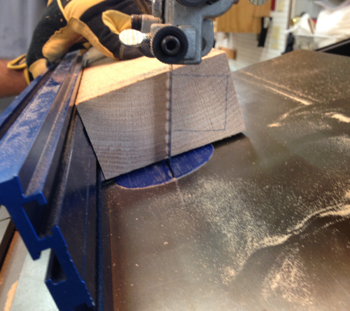
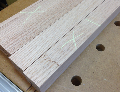
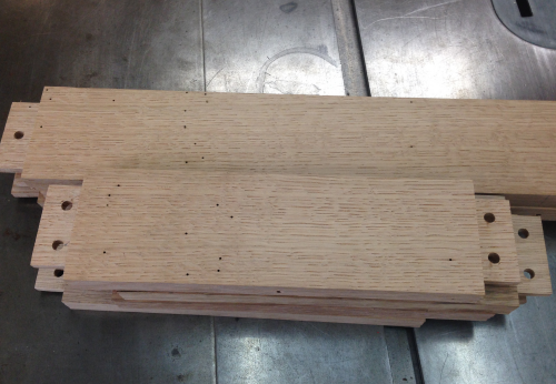
The main slabs for the two table tops came from the leaves of the table. The inlaid tile section will be cut down with a track saw on the MFT3 table. |
 |
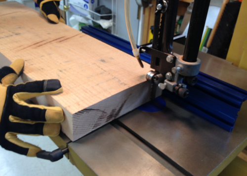
The material is a little less than 1 3/8 inches thick. |
 |
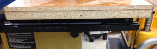
The cut-off provides the first look at the make-up of the slab. There is a thin veneer on the bottom, ~7/8 inch composite board, a thicker sandwich veneer, ~3/8 inch composite board with a veneer top. This all adds up to a little less than 1 3/8 inches. |
 |
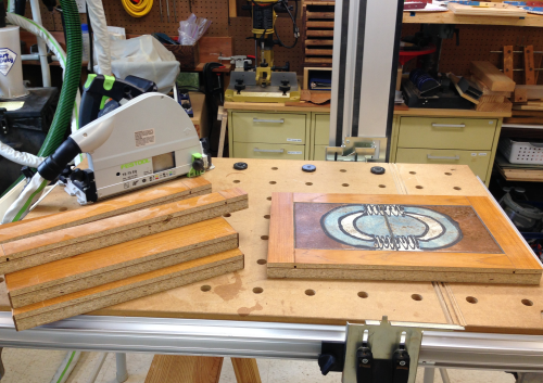
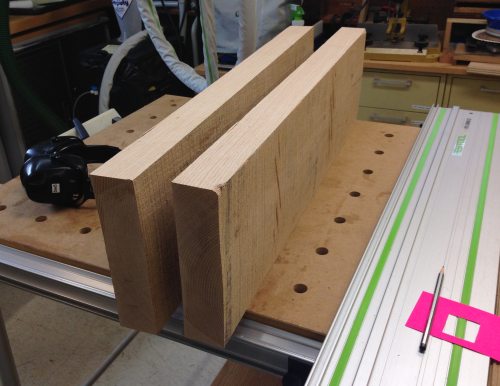
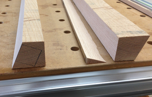
Here are the cut-offs and the slab. |
 |
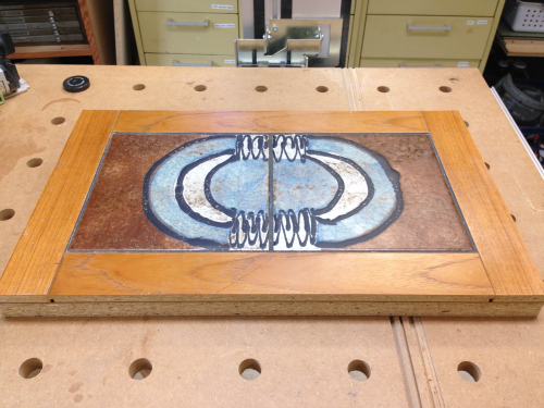
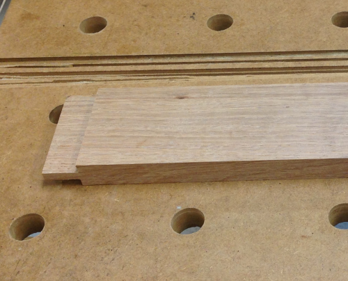
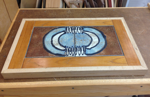
The table top slab after the trim. |
 |
x 2... |
 |
Each slab will be banded with a piece of oak 3/4 inch thick by 1 1/2 inches wide. The bandings will be mitered at corners. Test piece to see how the grain might look. |
 |
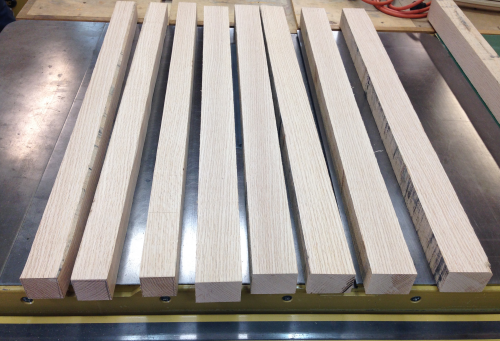
The lower section will have 2 3/4 inch wide aprons milled from some 4/4 and 5/4 stock oak planks I had in storage. We will mill them and finish at 3/4 inches thick. |
 |
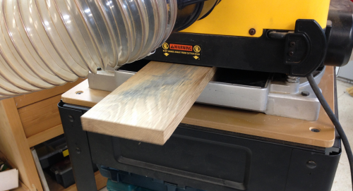
Jointing a face at the Powermatic. |
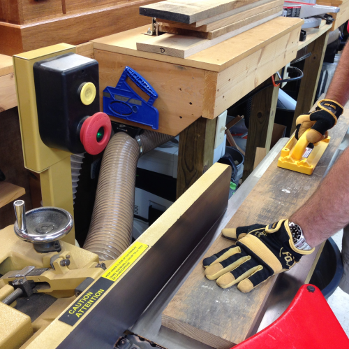 |
One side of each board was jointed and surfaced.
|
 |
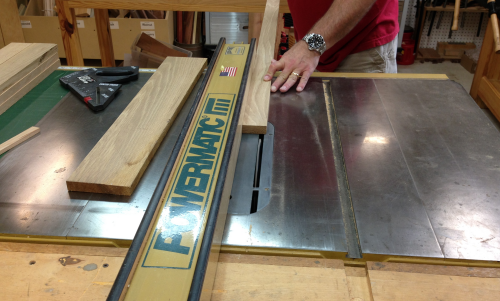
Then an edge was jointed square to that face. |
 |
Then the other face was surfaced at the planer and all boards were reduced to 3/4 inch. |
 |
Then all banding (1 1/2 inch) and apron (2 3/4) blanks were ripped to size. |
 |
And chopped to rough lengths. |
 |
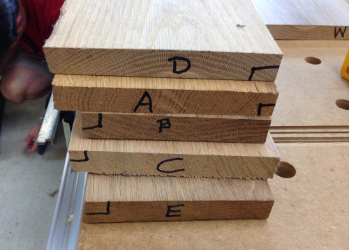
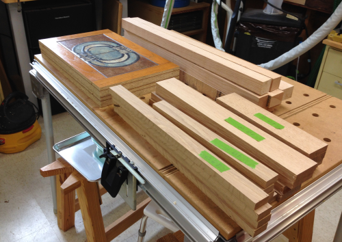
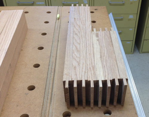
All the materials ready for final prep and joinery. |
 |
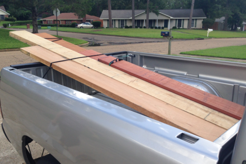
Cindy and I went to Picken's Hardwoods for a wood haul. In addition to the oak for this project we also secured some cherry, sapele and padauk. |
 |
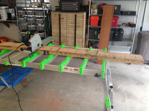
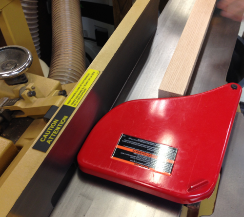
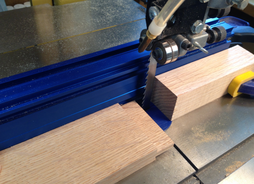
The oak 8/4 slab is nine+ inches wide by 10 feet long. We off-loaded the slab onto the BenchMark table. We crosscut the slab with the track saw. We then took the 5 foot long sections to the shop. |
 |
James and I further cut the slabs into 30 inch long sections and then we jointed an edge. |
 |
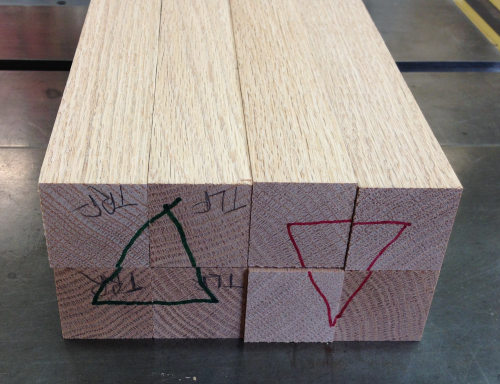
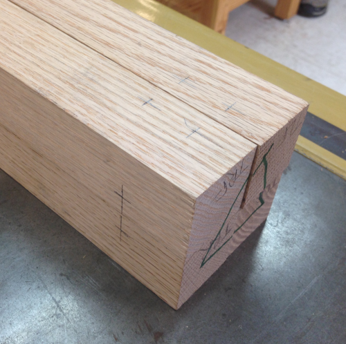
We examined the end grains looking for good rift patterns and cutting angles.
|
 |
We made sure of the rift sawn grain runs using a template to find grain running from corner to corner on the end of the piece. This guarantees that all four faces of the legs will have nice straight grain runs. |
 |
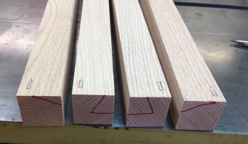
The grain on this slab ran nicely and five of the blanks just needed square rips on the bandsaw. |
 |
Three of the blanks would require angled cuts to get the rift sawn pattern to run from corner to corner. |
 |
This meant a table tilt at the Powermatic. |
 |
These angled cuts make for strange cut-offs. |
 |
But all of the blanks turned out nicely...this image shows the blank was cut a little fat on all sides to give plenty of wood for the milling at the jointer. |
 |
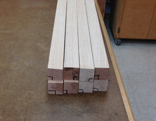
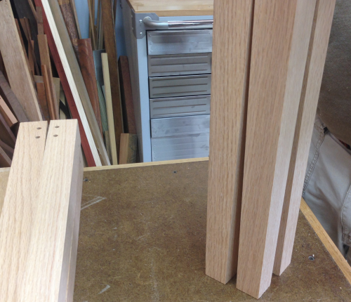
Eight oak leg blanks. |
|
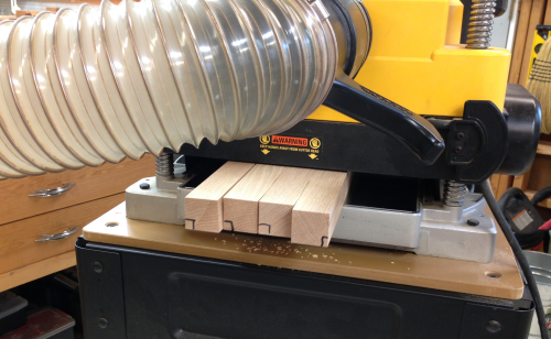
Jointing at the Powermatic. Run on a single face and then a second to square an edge. |
 |
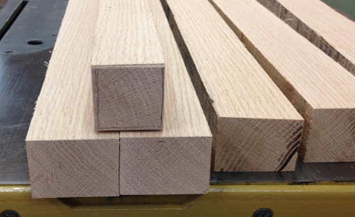
Squared blanks were then ripped to 1 9/16. They will sit a bit to de-tension and then they will all be planed to 1 1/2 inch square blanks. |
 |
After de-wonking, the boards were run through the planer on the two unworked surfaces. |
 |
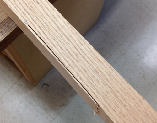
We had one blank that had a real issue due to a fence failure at the bandsaw. |
 |
We planed down to a point that we could live with...approximately 1 3/8 squares and we had enough length to remove any bad ends. The blanks were all chopped to 20 inches. |
 |
After the blanks were selected for grain runs the matchups were marked on the end for easy layout. |
 |
A quick layout of mortise locations was made...matchups were confirmed. |
 |
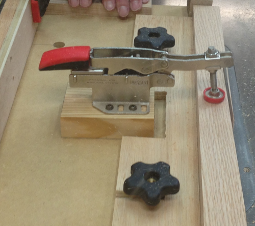
The mortises were cut on the PM dedicated bench mortiser. |
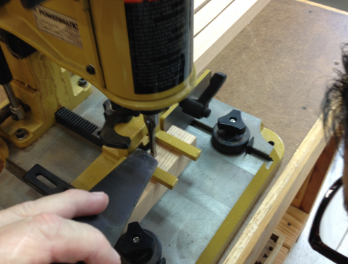 |
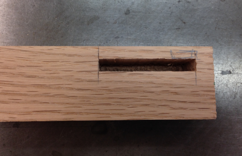
The mortise was 1/4 inch wide, two inches long, and one inch deep. |
 |
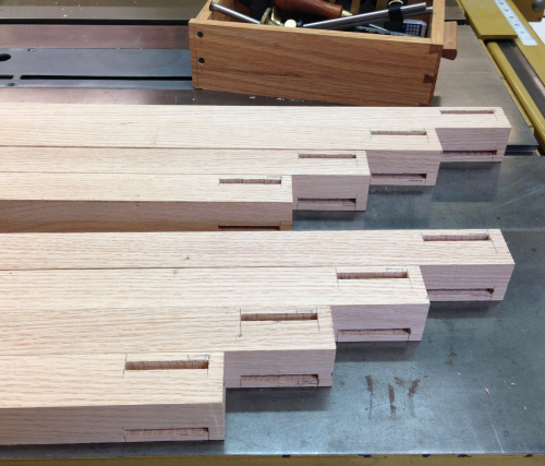
The sixteen finished mortises... |
 |
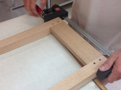
To calculate the apron lengths...we wanted the table base to sit slightly inside of the edge banding that will be attached to the slab edges. To get a real world length we used two legs and then measured to the end of the slab. At 17 inches it was slighly shorter than the slab.
|
 |
So we added the 17 inch shoulder to shoulder measurement to 1 3/4 inch (two 7/8 inch long tenons) and then came off 1/32 for good measure and tried a pine crash test dumm dry fit...looked good. We did the same for the short aprons...they ended up being 9 1/8 shoulder to should and 10 7/8 inches including the tenons. |
 |
We chopped all of the apron lengths...and then made the tenon depth cuts at the PM66. We brought out the Vega tenoning attachment. |
 |
The first round of cuts...all of the cheek cuts are made. |
 |
The second tenon cut was also made at the P66. We used the Incra mitre gauge with its nice stop mechanism to gain repeatability. |
 |
Then the shoulder cuts were made |
 |
The tenons came out pretty clean. |
 |
Done at the tablesaw... |
 |
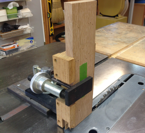
The edge shoulder depth cut was made at the bandsaw with the fence and a stop block defining the cuts. |
 |
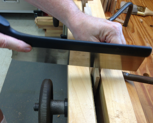
The edge shoulder crosscut was made by nibbling the small piece off with a hand saw. The material was held in the Moxon. |
 |
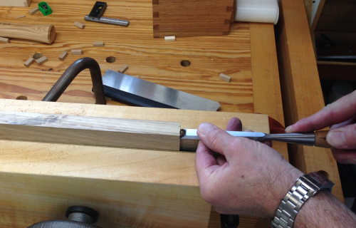
The fit was completed with shoulder planes and sanding... |
 |
Or chiseling as needed... |
 |
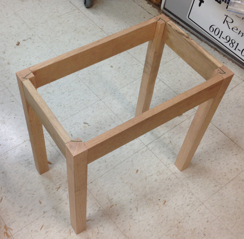
A dry fit to see how the apron/leg carcase will look. |
 |
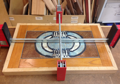
The top slab tested for fit... |
 |
Edge banding held up for a visual... |
 |
Side look of the banding and apron. |
 |
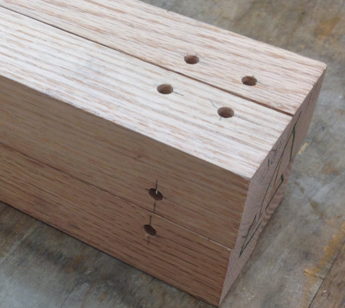
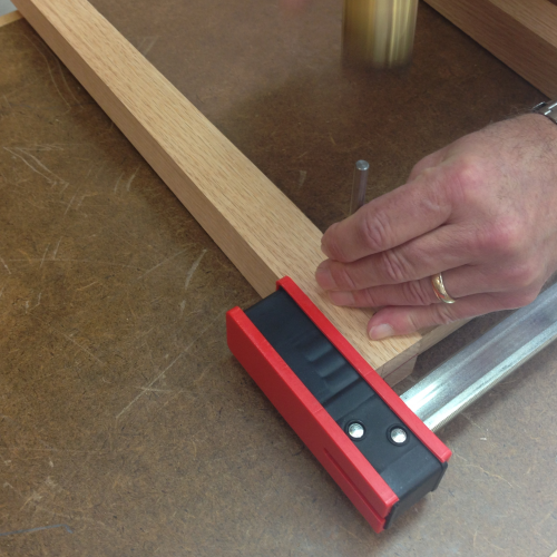
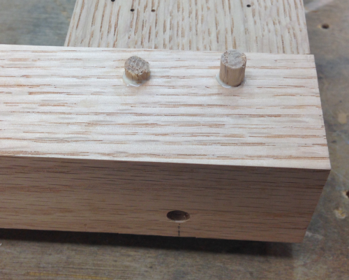
Legs all received drawbore pin holes...two each on the short apron tenons and one on the long apron tenons. This layout mark put the hole at 7/16 inches in which will roughly center the hole in the length of the tenon. |
 |
The double drawbore holes were at 7/8 and 1 7/8 inches...the single was at 1 3/8 inch. |
 |
The holes were punched at the drill press with a 1/4 bit. |
 |
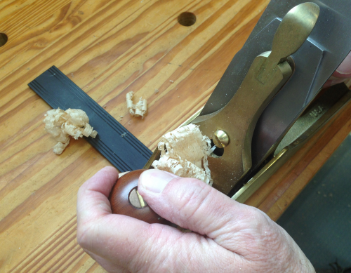
The outer faces of the legs (those that will not be tapered) were planed lightly with the LN #4 with the high angle frog.
|
 |
The legs then went to the tapering jig at the PM66. The setup created a top of the leg that is 1 1/2 inches and the bottom of the leg that is 1 1/8 inches. |
 |
The taper cut was made... |
 |
...and then the blank was rotated 90 degrees and a second taper was made. |
 |
A visual of the tapers... |
 |
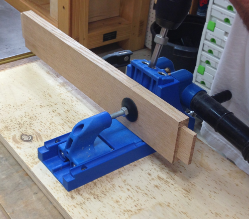
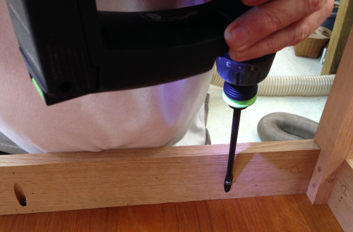
Before glue up begins, Kreg pocket screw holes will be drilled to connect the aprons to the top. |
 |
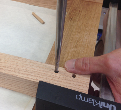
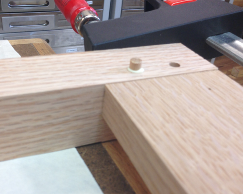
The tenons were inserted into the mortises and the 1/4 inch drill bit was placed into the drawbore hole and then tapped with a hammer. This marks the location of the hole... |
 |
...the holes were actually drilled about 1/16 inch closer to the shoulder. |
 |
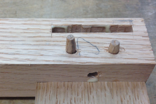
Then a clamp pressed the mortise/tenon joints and the holes were inspected... |
 |
...a drawbore pin was used to align the three holes... |
 |
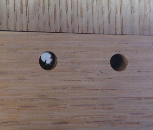
...close up of a hole. All milling is done, assembly is next. |
 |
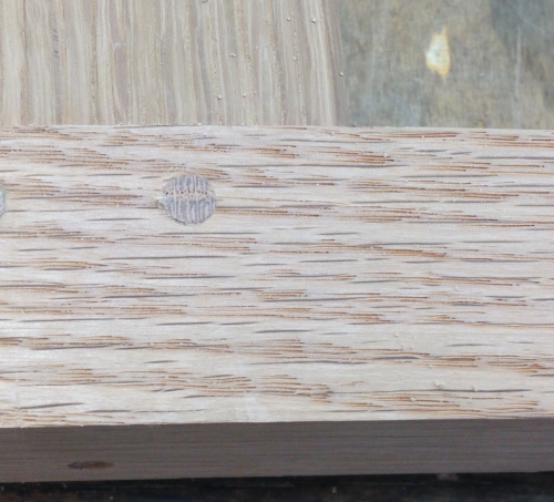
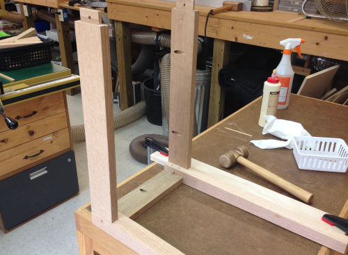
Glue up began on the end frames...a 1/4 inch oak dowel was pounded in the hole...drawing the joint tight. |
 |
The dowels were left protruding slightly... |
 |
...and slightly proud in the back...they will all be cut flush after the glue sits up. |
 |
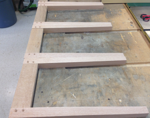
All of the end apron / leg joints are done. |
 |
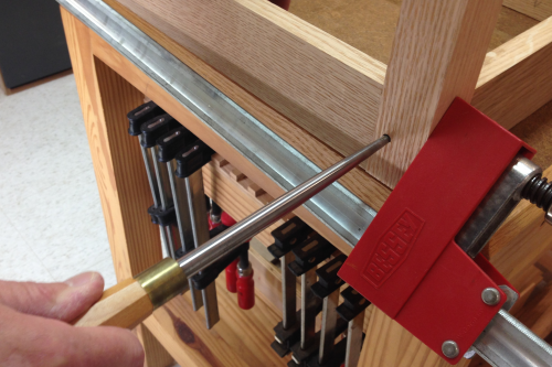
The dowel ends were sawed off using a Japanese flush cut saw with no set. |
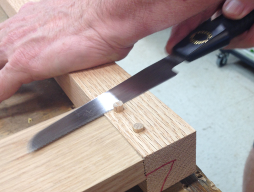 |
Nice and flush dowel...joint drawn tight. |
 |
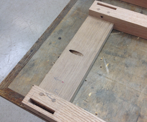
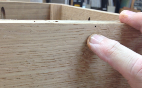
Backside of apron showing flush cut dowels, mortise drawbore holes awaiting the long aprons. Also visible is the pocket screw hole. |
 |
Adding the long aprons to the end frames came next...a quick dry run with clamps was performed to make sure all the mortise/tenon joints looked good and to make sure no glue had fouled the mortise from the first round of joinery. |
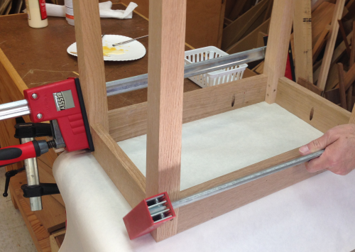 |
Then the joint was glued and assembled... |
 |
...the clamps and the draw bore pin made the lineup fall into place and pull up tight... |
 |
...after all the pins were pounded in... |
 |
...some Timber Mate red oak putty went into any holes or flaws. |
 |
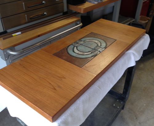
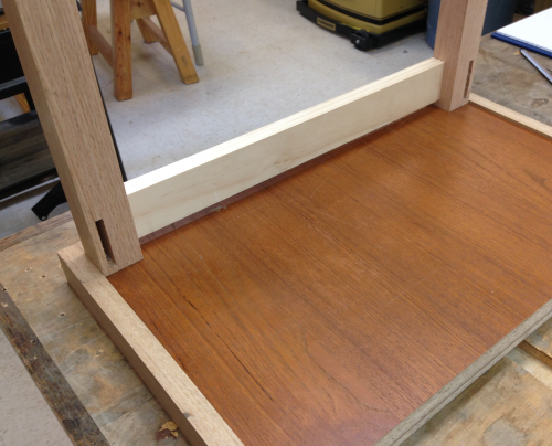
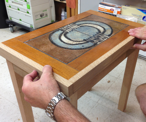
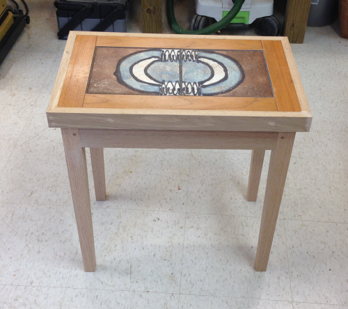
A quick look at how the tops sat down on the frames.
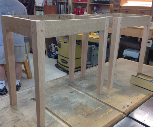
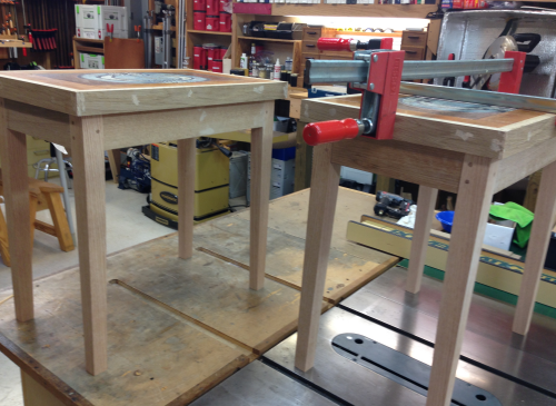
The lower assemblies are complete. |
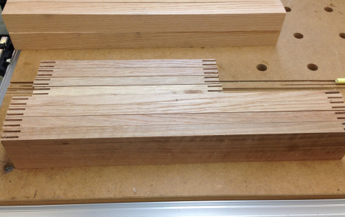
 |
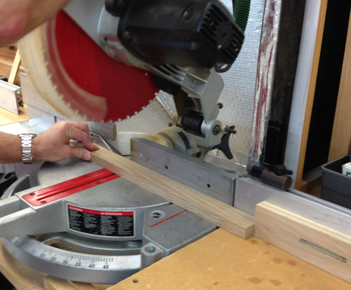
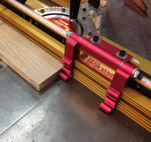
The bandings for the top slabs needed to be mitered to length at the chop saw. We created a new throat plate out of MDF as well as installing temporary back plates. This was to minimize spelching on the back side.
|
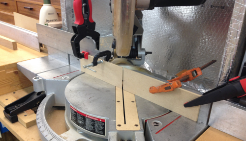 |
All the miter cuts were with the saw at 45 degrees to the right...the setup here is to cut all the long banding pieces the same length. |
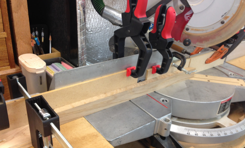 |
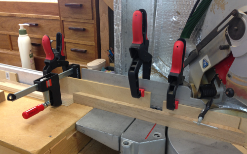
The same was done to cut all the shorter runs... |
 |
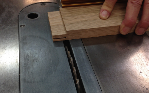
The banding edges were glued and nailed with 1 1/2 inch 16 gauge brads. The mitre joints were tacked with 1 inch 23 gauge headless pins. |
 |
A banded top slab. |
 |
Clamped... |
 |
Dry fit for the top slabs... |
 |
Corners look pretty good... |
 |
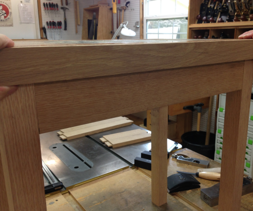
The apron assembly was secured to the undertside of the top slab with Kreg pocket screws. |
 |
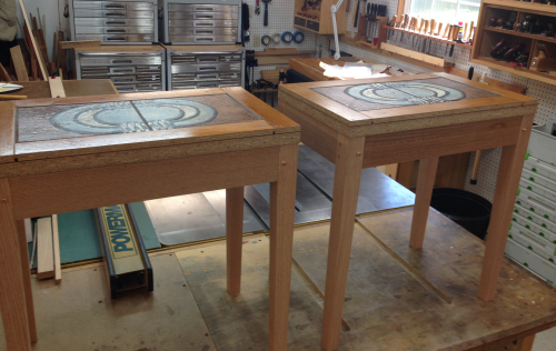
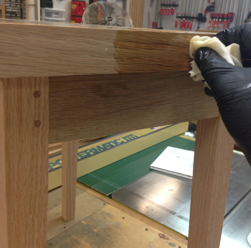
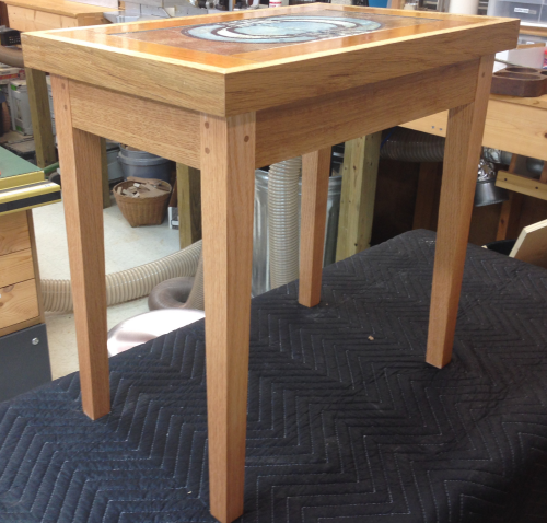
Ready now for a final sanding...and then some finish coats. |
 |
Hope's 100 percent pure tung oil was rubbed on. |
 |
After a coat... |
 |