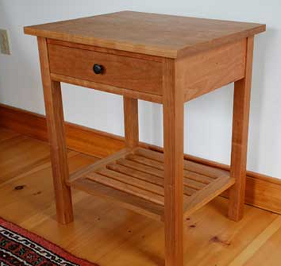
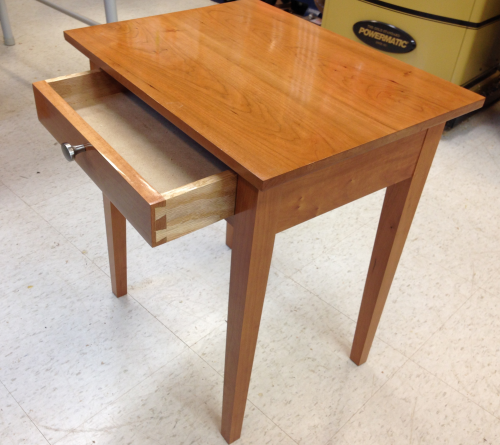
This table will be used between a couch and comfortable chair. The height was defined by the ease of use from both pieces of furniture. This image is pulled from the Internet...it is a mission style cherry table that Cindy and I both liked in regards to proportions. We want the one drawer but not the lower shelf.
|
 |
This is the preliminary Sketchup design. The proportions were all downsized (to about 85% of the orignal) to suit our size requirements. The top will be breadboarded on the ends. The center pieces in the top will be curly cherry (brought to me from Virginia by my brother Tom) and will be book matched. The rest of the table will be cherry.
|
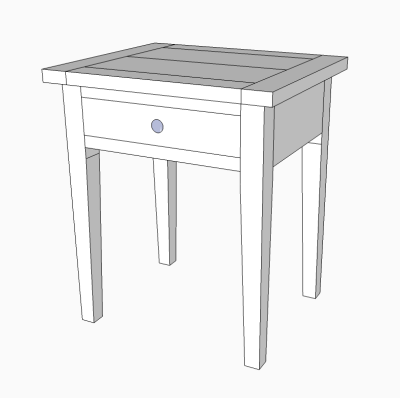 |
Top will be glued slab with bread board ends. Legs will be 1 1/2 inch squared at the top and tapered on the inside faces. front drawer apron top will be sliding dovetail joint. the lower will be mortise and tenon. all other apron sides and back will be dual mortise and tenon.
|
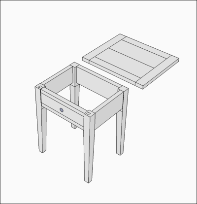 |
The original design has undergone some changes...we decided no curly cherry on the top with no breadboard ends. Some of the wood dimensions, especially thicknesses, will change based on milling results. |
 |
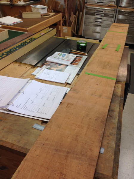
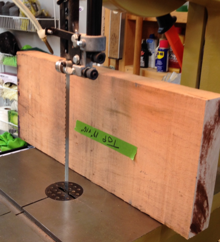
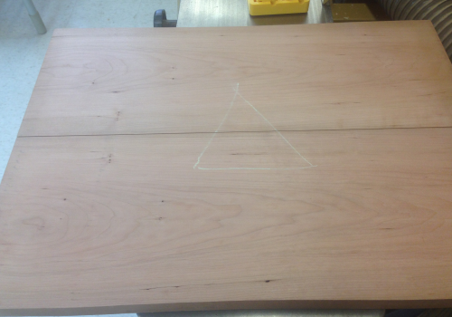
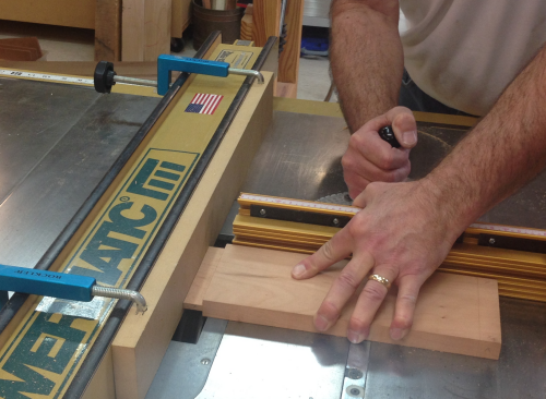
I bought a couple of 8/4 slabs of cherry. They were about 8 inches wide by 8 feet long. Here one of the slabs is being marked up to be sub-divided into three slabs. The layout was assessed to avoid sapwood and provide good grain patterns. |
 |
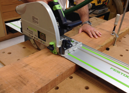
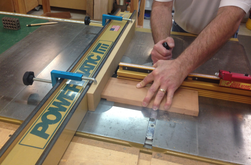
The slab was cut down using crosscuts on the MFT3 table. |
 |
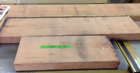
The three slabs were for the legs, the table top, and the aprons. |
 |
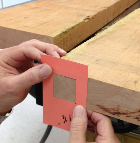
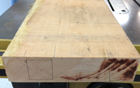
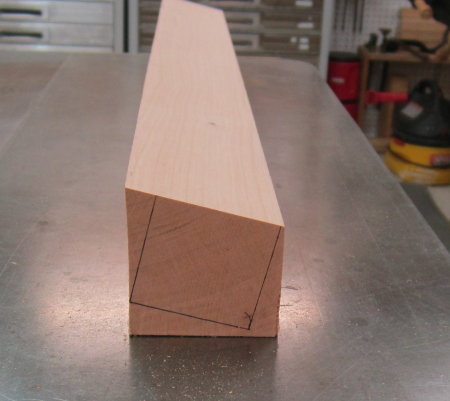
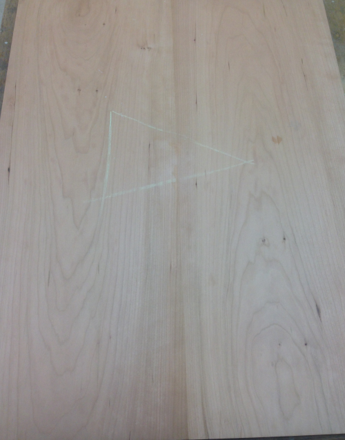
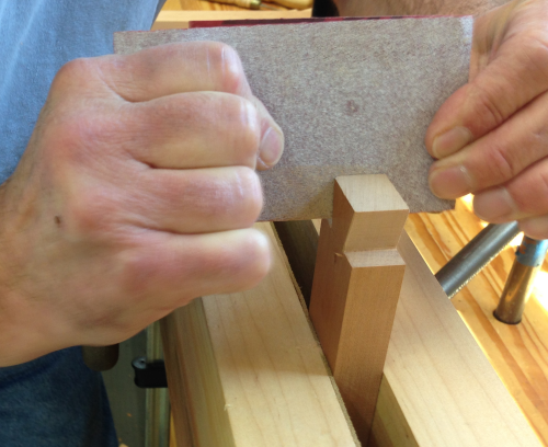
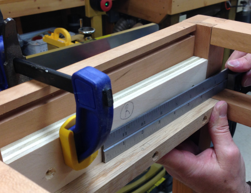
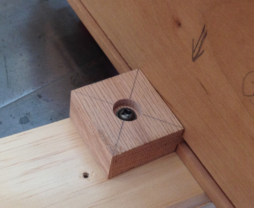
In particular, close attention was paid to the grain pattern for the legs. Taking a tip from Michael Pekovich (Fine Woodworking No. 243) we used a template to provide a window to lay out the legs so that the grain runs diagonally from an edge to an edge. |
 |
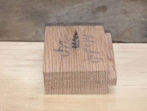
One of the blanks had a grain run that required cut rotation to maximize the straight grain. |
 |
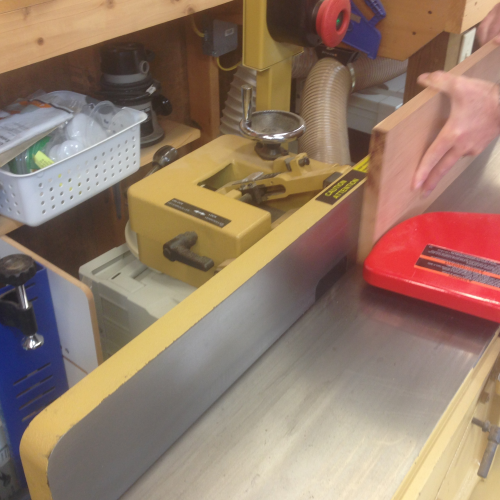
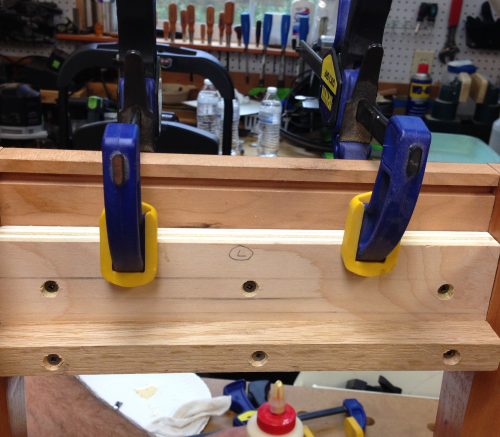
The blanks were jointed on one edge. |
 |
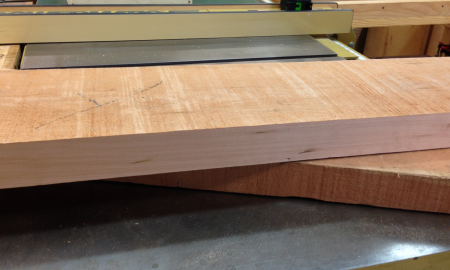
The jointed edge...our first real look at the color and grain. |
 |
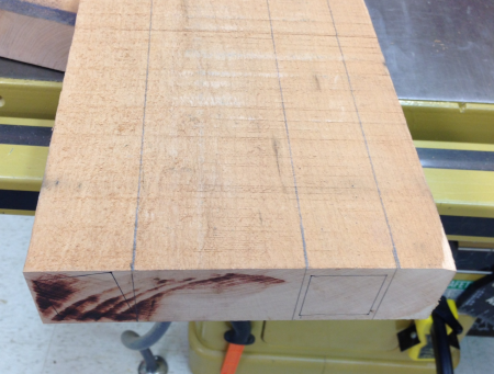
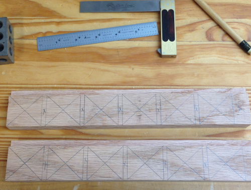
Here are the layout marks for cutting the leg blanks. |
 |
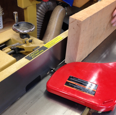
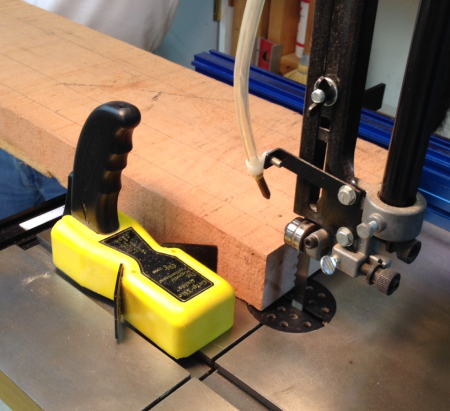
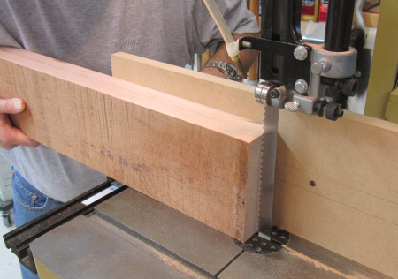
The jointed edge was placed against the fence and the blanks were sawed on the bandsaw. |
 |
When it came to resawing the larger top plank we ran into problems with the blade overheating and wandering in the grain. The bandsaw blade, a 1/2 inch "Woodslicer", had been a great blade but it had seen too many cuts.
|
 |
So we put on a new Woodslicer blade, a 5/8 inch, and it really rocked. |
 |
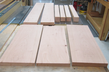
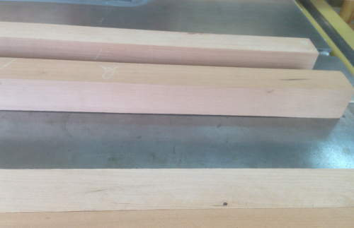
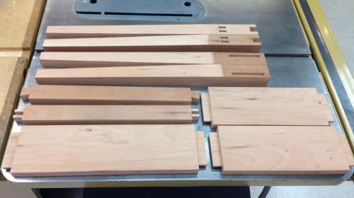
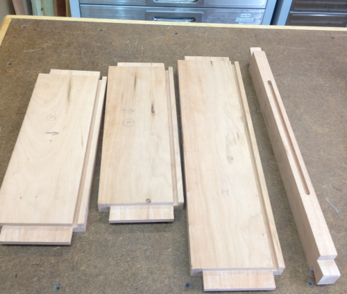
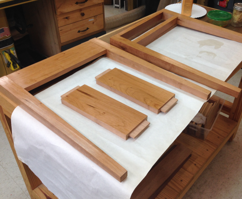
The parts, after the first milling phase...top slats in foreground, aprons at left and leg blanks on the right. |
 |
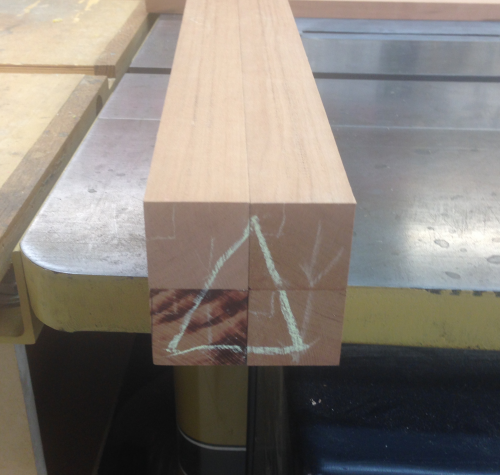
The one leg blank that needed rotation to enhance the grain run was cut at 13.3°...this was to provide a riftsawn leg with tight, straight grain along each face. |
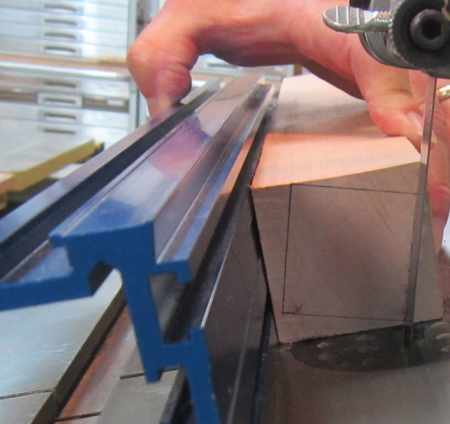 |
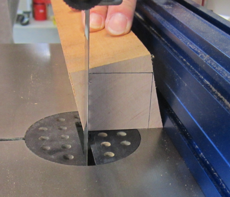
The cut squared one face... |
 |
The table was then returned to 90° and all the sides were squared. |
 |
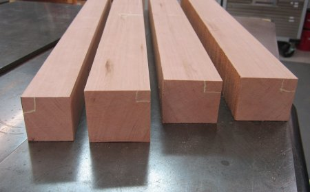
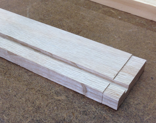
The other three leg blanks had a face jointed to make it even and another face jointed to make it square...the blanks were then ripped on the table saw to create the four sides. These are roughly 1 1/2 inch blanks...they will finish out about 1 1/4 inches square. They are riftsawn and ready for the planer... |
 |
After the legs were planed they went back into storage for a few weeks. One of them managed to go wonky...you can see the arc at the bottom of the leg against the cast iron saw top. |
 |
So all legs went back into the planer... |
 |
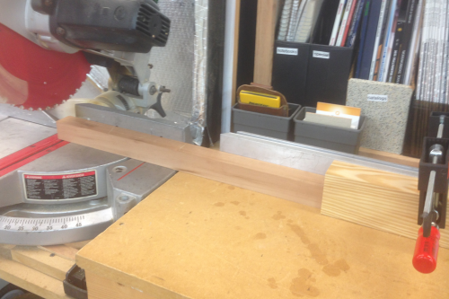
Then they were all cut to length... |
 |
All faces were checked for grain and to determine the show faces...then they were marked. |
 |
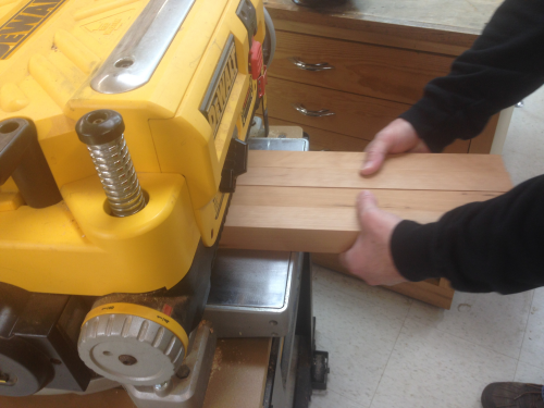
The two boards that will make the top were selected...they were then run through the planers a few times to clean some surface issues. |
 |
Then they were jointed on the PM to prepare for glue up. |
 |
Edges were glued... |
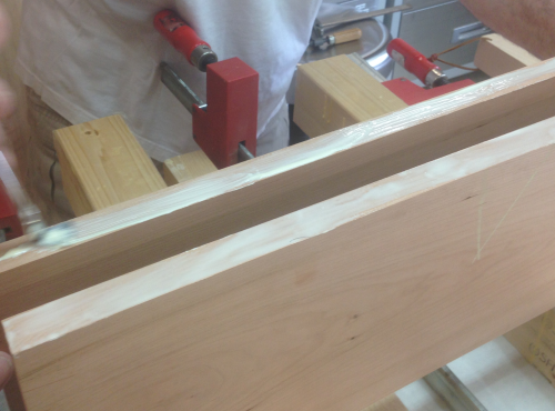 |
A caul was used to hold the two pieces coplanar...Bessey K clamps provided the side to side for the squeeze out. |
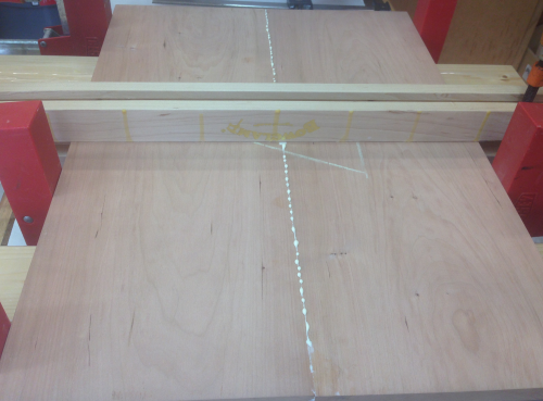 |
The clamping setup... |
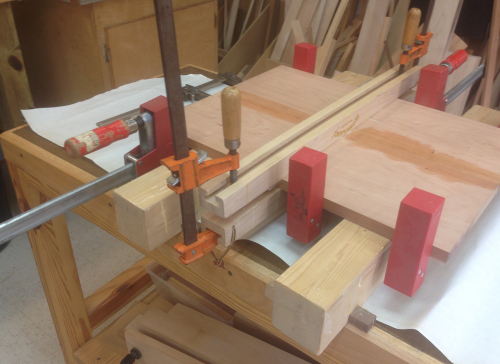 |
...led to the top having an almost invisible glue line. |
 |
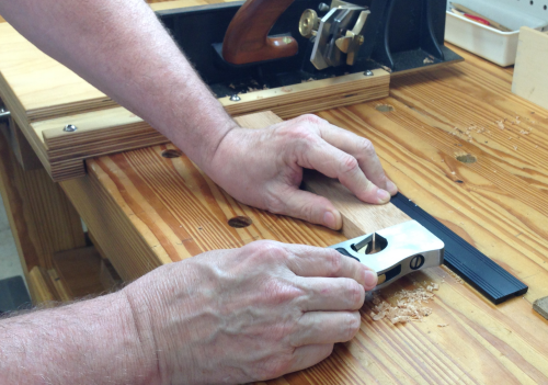
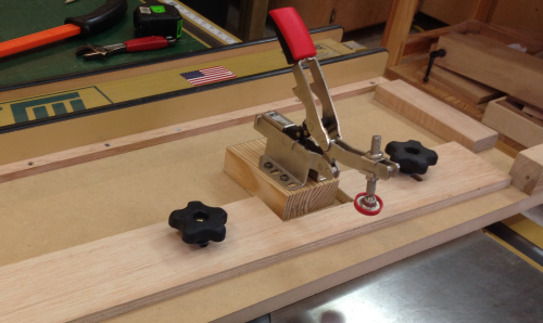
The side and rear aprons will have a tenon on each end...these were laid out and then the tenon cheeks were made on the Powermatic with a dado setup that was set into a sacrificial fence. This image shows the first run... |
 |
Then the board was flipped to create the other cheek. |
 |
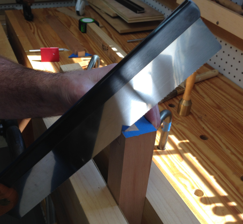
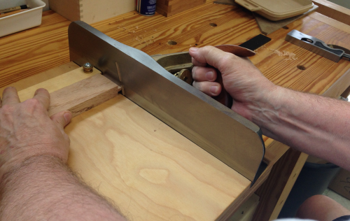
Backsaws were used to complete the tenons...crosscut. |
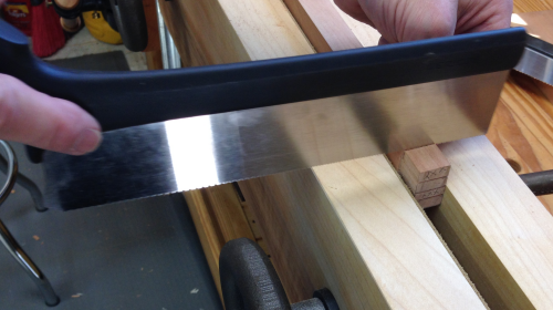 |
And the ripcuts. |
 |
The completed apron tenons. |
 |
The top rail dovetails will fit into hidden dovetail sockets...here is the leg marked out. |
 |
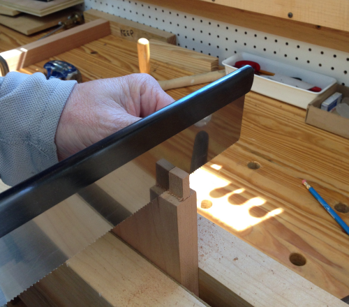
The hidden dovetail sockets were first cut on the angles with the Bad Axe Stilleto. The back edges were then squared up by beating a cabinet scraper edge into the saw kerfs. |
 |
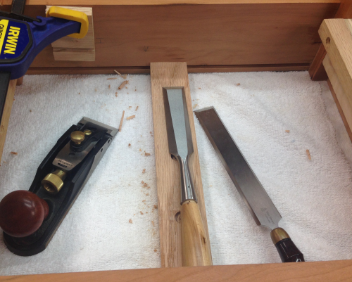
The sockets were finished out with chopping and paring with chisels. |
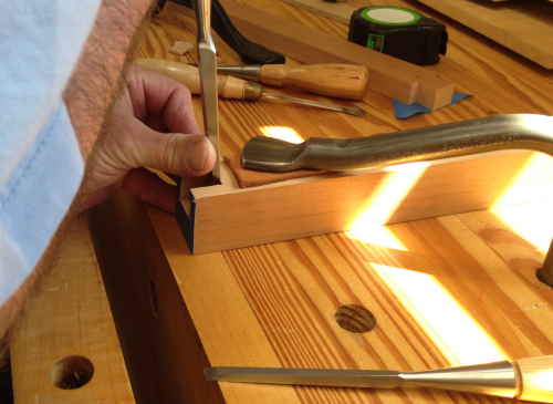 |
The edges of the dovetails were knocked back with a little sandpaper wrapped arount a cabinet scraper. |
 |
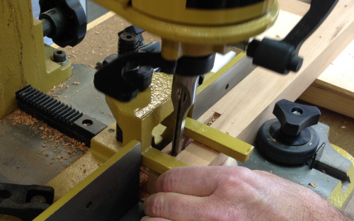
We drilled the mortises with the dedicated Powermatic benchtop mortiser...1/4 inch mortises. |
 |
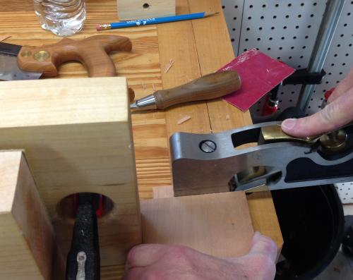
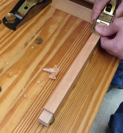
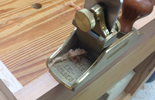
We cut the tenons a little fat so that each could be trimmed to fit into the mortises. Most of this trim was done with a shoulder plane. |
 |
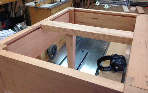
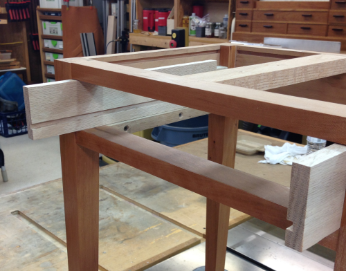
The back apron dry fit into the back legs. |
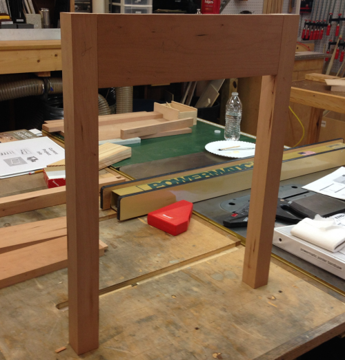 |
Image shows the inside structure where the apron tenons fit into the leg mortises. |
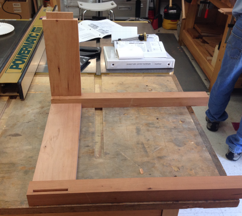 |
Dry fit of the side apron. |
 |
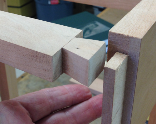
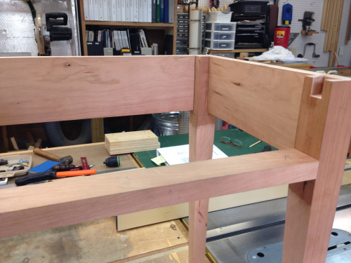
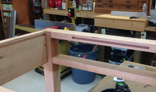
Close up showing how the side apron comes into the front right leg with the tenon. The top rail fits into a hidden dovetail socket. |
 |
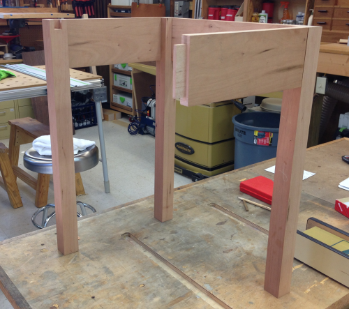
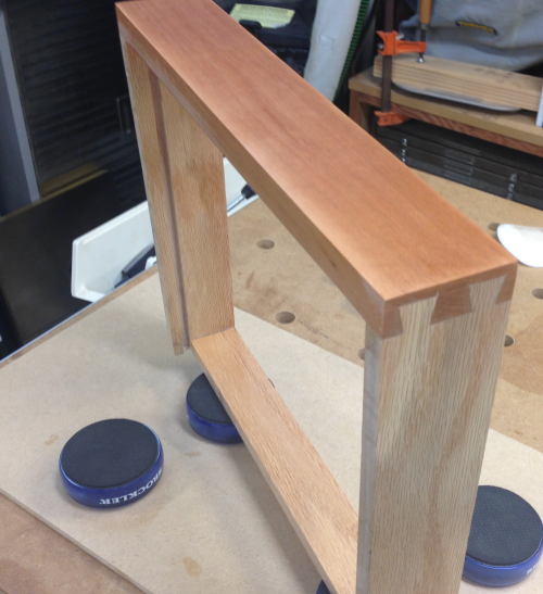
Dry fit of the front top rail into the hidden dovetail socekets. |
 |
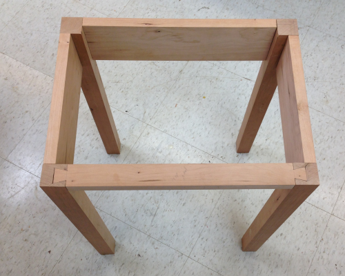
View from top showing the hidden dovetail joints. |
 |
Side view of the apron... |
 |
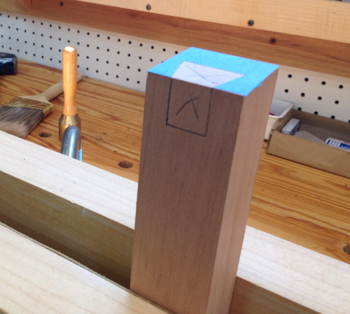
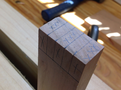
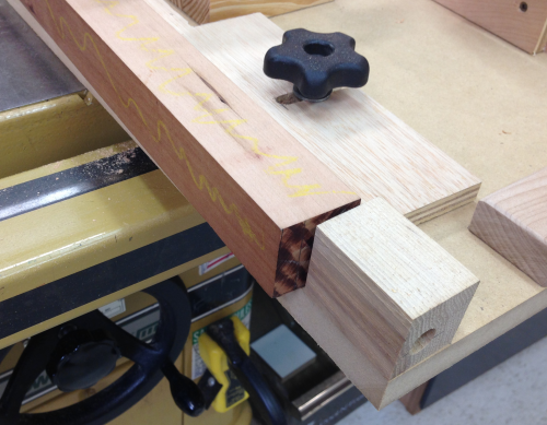
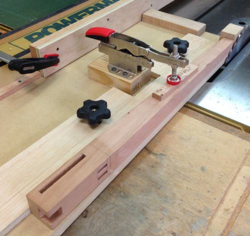
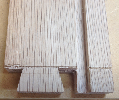
The front lower rail will be secured to the legs with twin tenons. Here the legs are marked out...ready to mortised. |
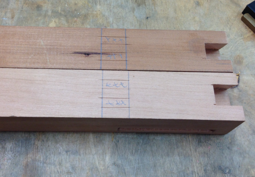 |
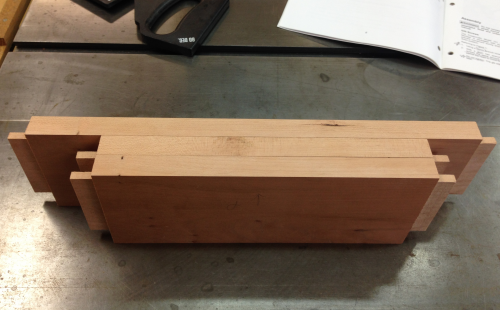
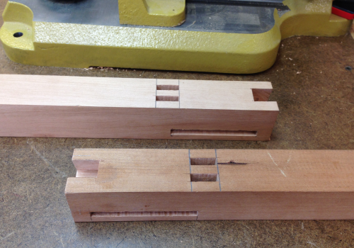
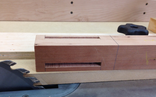
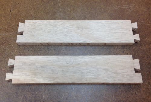
Front legs with all milling done...side connection is the long mortise, front lower rail with twin mortises, and the front top rail with a hidden dovetail socket. |
 |
The tenons were marked out from the actual twin mortises. A rebate is visible at the top of tenon...this will help improve the appearance of the show side of the joint. |
 |
The edges were nicked with blade. |
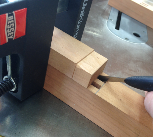 |
The lines were then extended...the cuts were made with backsaws and then chiseled. |
 |
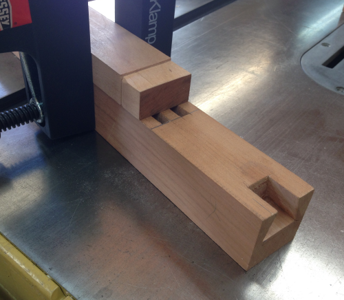
After a dry fit adjustments will need to be made... |
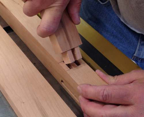 |
...these were done with paring chisels, sandpaper wrapped on a cabinet scraper, and/or rasps as needed. |
 |
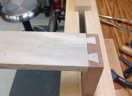
Joint dry fitted. |
 |
All of the main components are milled and with a few tweaks, some grooves for the buttons, some planing and sanding and they will be ready for the glue up. |
 |
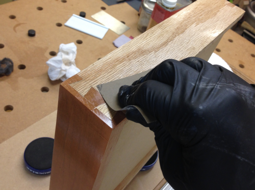
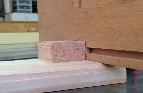
Some surfaces were planed so that they would have a shadow line after the joint was completed. Here the front top rail is planed back.
|
 |
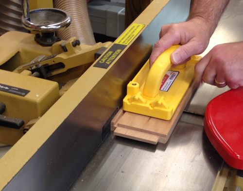
The aprons were planed at the jointer. |
 |
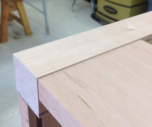
Here is an example of the shadow line created... |
 |
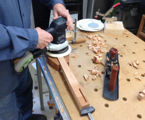
Other surfaces were planed for smoothness... |
 |
...and then sanded up to 320x. |
 |
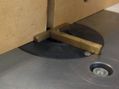
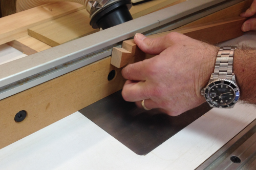
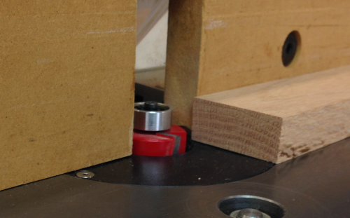
The grooves for the cabinetmaker's buttons were made at the router table with a 1/4 inch compression spiral bit. The groove was to be 1/4 inch from the top edge and 5/16 inch deep...the layout was made with brass blocks. |
 |
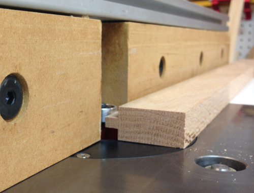
The side aprons and the back aprons were through grooves. |
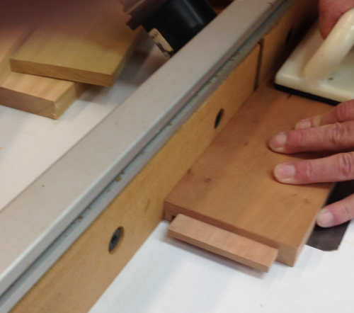 |
The front top rail received a groove that was stopped at both ends so that the groove would not interfere with the dovetail joint. Here James is dropping the front rail down onto the bit. |
 |
The finished grooves... |
 |
...how the grooves look inside the apron. |
 |
Final step before the glue up was cutting a kicker rail...this will be screwed to the underside of the top... |
 |
...as shown here the kicker rail floats in the same grooves as the buttons...during the dry fit it was obvious that rail was a little to long...when the sides were clamped the rail would bind...thus negating its purpose. |
 |
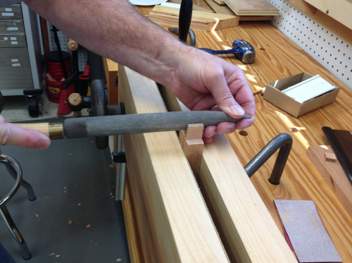
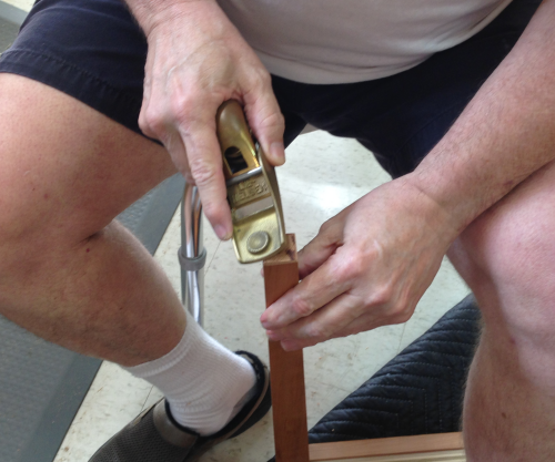
To fix this I planed the tenon shoulders with the small LN shoulder plane... |
 |
...and trimmed the ends of the tenons with LN shooter. |
 |
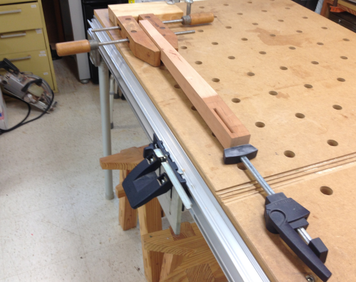
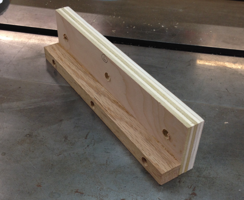
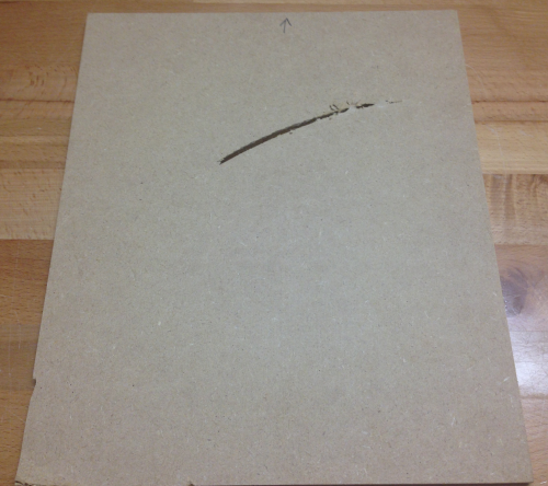
As James and I prepared to taper the legs we brought out a newly finished taper jig that was to be used on the table saw. We had a track blowout when we were applying pressure with the toggle clamp. This jig would not do. |
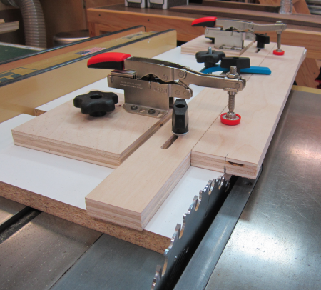 |
| So we changed our focus to the building of a new taper jig #2. |
 |
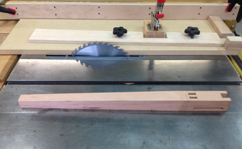
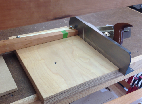
The end of the leg to be tapered is placed against the stop block and is aligned with taper mark lines... |
 |
The marking line for the top end of the taper cut is placed so that the work piece is coplanar with the sled at that point. The entire sled has been pulled off the blade by 1/32 inch so that the cut is "fat" and will be touched up with a jack plane. |
 |
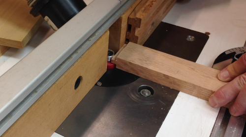
The sled is pushed through and the leg is tapered. This is the second taper on this leg so a shim is used at the clamp. |
 |
The finished product...the four legs are now ready for cleaning up the saw marks with a jack plane. |
 |
Injury fix...when the first taper jig failed, James and I tried to taper the legs with a makeshift jig on the bandsaw...it went wonky and put a wound into our leg. During the tapering with the new jig we managed to alter the taper to remove most of the injury. |
|
But some still remained... |
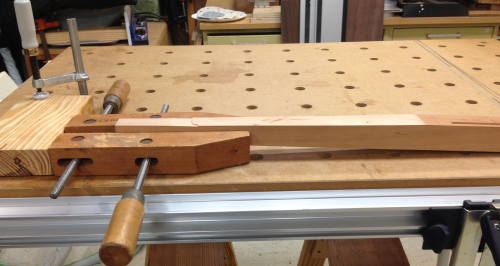
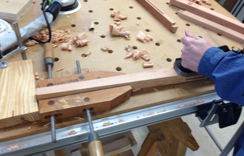
I secured the leg on the MFT3 table.
|
The end was elevated to make the actual planing somewhat horizontal.
|
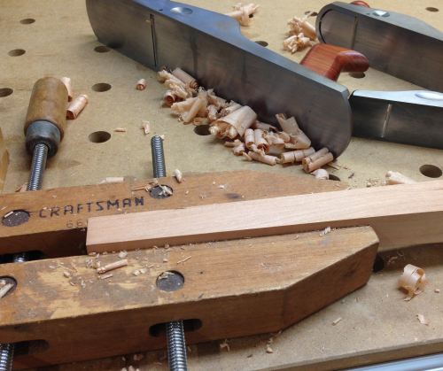
I attached the leg with a block plane, then a smoother and then a #5 jack. Injury healed.
|
The glue up began with the front rails attaching to the front legs. |
 |
Second step was gluing up the back apron to the rear legs. |
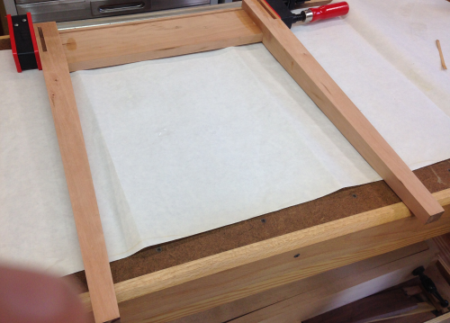 |
After the sections were varnished, a quick dry fit to make sure all is well... |
 |
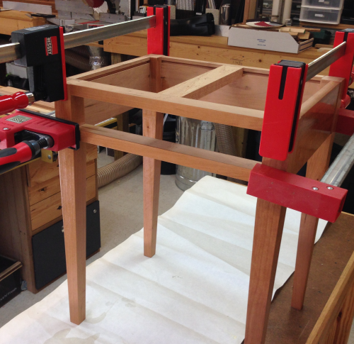
..then the front and back pieces were glued up with the side apron panels...with the kicker rail floating in the grooves. |
 |
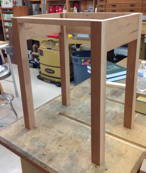
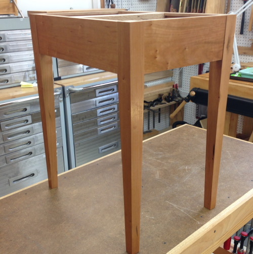
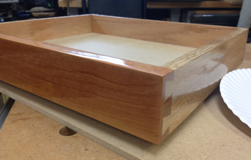
The lower assembly. |
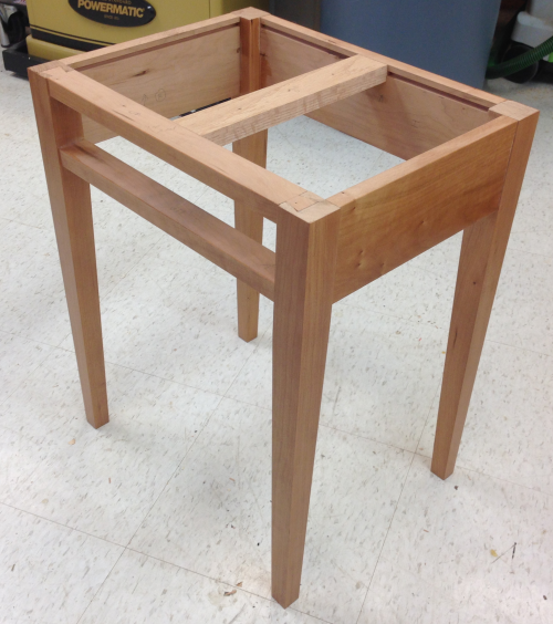 |
There was a slight wobble when the assembly was placed on the floor. To remove this, the long legs were marked with tape and material was removed from the bottom of them until the wobble was gone. First the edges of the bottom of the legs were chamfered with the LN 102 to reduce spelching and prevent tearout when the table is moved across the floor. |
 |
We tried two processes to remove the material. Cindy and I held the assembly on the shooting board and removed material with LN 51. This worked well. The other process was to move the bottom of the leg across the LN 60 1/2 which was held in the Moxon vise. Cindy and I did not like this option. We shot the legs until the table sat well. |
 |
Each side of the table had to have a guide and a runner for the drawer. A oak runner was glued and screwed to a Baltic birch plywood guide. |
 |
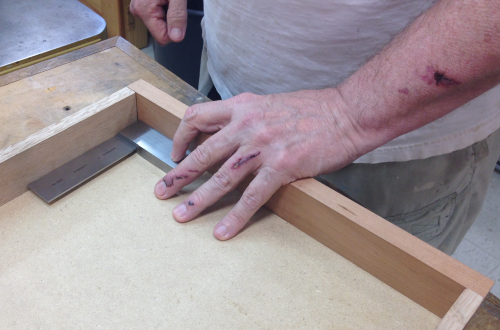
Runner was squared to the front lower rail... this made the runners go up slightly but kept them square to the front rail... |
 |
...and then the guide was screwed and glued to the inside of the apron. |
 |
The cherry front and the oak drawer sides were grooved (1/4+ inch ) for the MDF drawer bottom. |
|
The front piece was planed on the top and sides until it fit nicely... |
|
Then the oak drawer sides were planed until they ran easily into the frame... |
 |
Then rebates were let in to the ends of the sides for the dovetail layout. |
 |
The 1:4 dovetails were laid out on the oak sides...the tails were free hand sawed with the Stilleto and a crosscut backsaw, waste was cutout with KC coping saw and then finished with chisel chops and paring. |
 |
The sides also had a rear dovetail for joining with the back drawer panel. Here is the layout for the one large tail. |
 |
There was an issue with the planed rebate...it was ok on the right side of the image to the right...but it was off in the middle and on the left edge. This caused some issues with the overal fit... |
 |
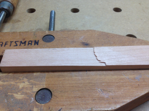
During the joinery I continued to have a problem with one of the rear fits...when I tried to use a rasp to fix the fit, I went in the wrong direction and made the gap worse...I will haveto mend a gap with a wedge. |
 |
The front half-blind joinery went well. Here is a dry fit of the oak side into the cherry front. |
 |
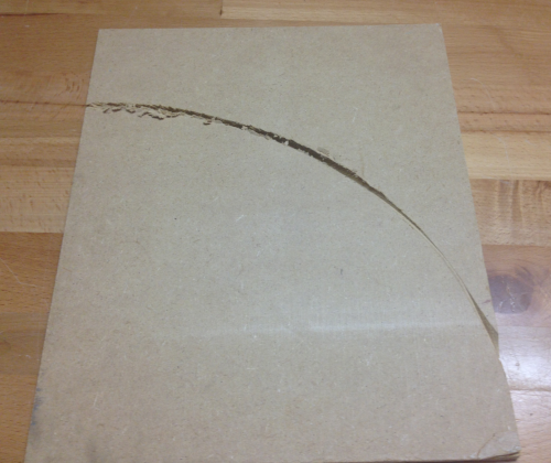
In preparation for the glue-up of the drawer, I was trimming a small piece off of the 1/4 inch MDF drawer bottom...when I had an accident, the cut-off tried to fall down into the blade insert on the P66...I glanced at it and that was enough of a distraction to misguide the work piece. It caught on the blade and was flung on to the blade. In this image you can see where it caught in the lower left corner. |
 |
This is the down side of the piece...it was driven across the blade in an arc and then shot towards my left hand and arm... |
 |
I received a blow to the forearm, a cut on the arm, a twisted wrist and some nasty ripped skin on the hand...but all in all I was very lucky. |
 |
A couple of days later my fingers moved well enough to get back at it...I recut the bottom of the drawer and dry assembled it...looks pretty good for square. |
 |
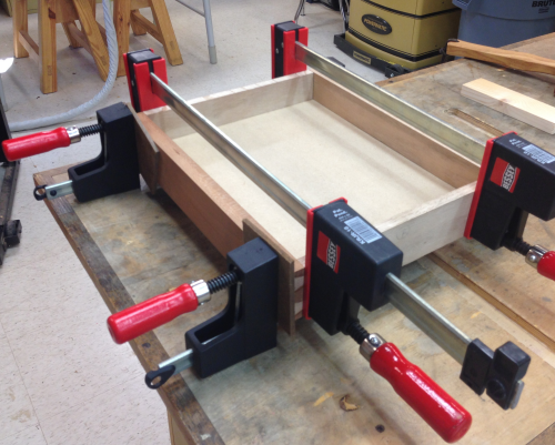
Glued and clamped. |
 |
| After clamps were removed the process of planing to fit started... | 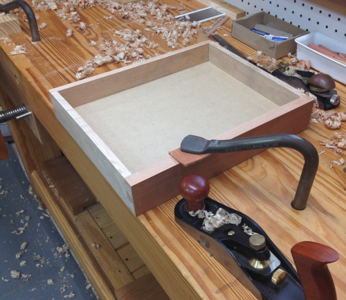 |
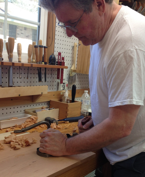
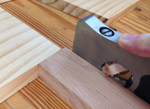
Some of the cherry grain on the top edge of the drawer front was diffictult to work...used the LN scraper plane to pull off some nice lacey cherry slices. |
 |
Due to the runners going uphill slightly the back of the drawer was binding against the kicker in the back of of the carcase, rather than lowering the back of the drawer I removed some stock off the bottom of the kicker board. I did this with a paring chisel and the chisel plane. When I needed a little more oomph I put the long chisel handle on the LN bench plane and then beat on it a bit. |
 |
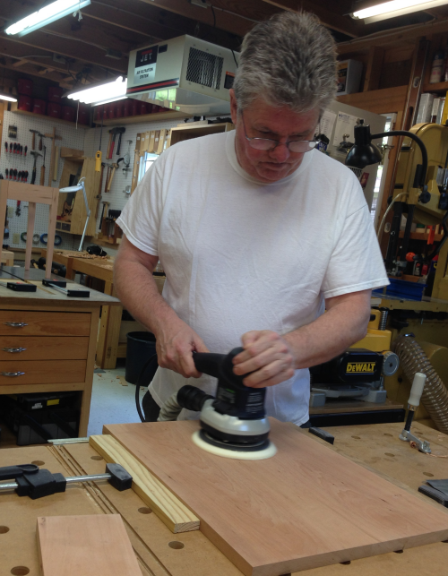
After sanding up to 400x with the 150mm sander, everything was then hand sanded with 400x to remove squigglies. First coat of Super Blond shellac was padded on...and then a second coat. |
 |
Then started layering with wiped-on Waterlox ®. |
 |
A quick look at the drawer dovetails in the table... |
 |
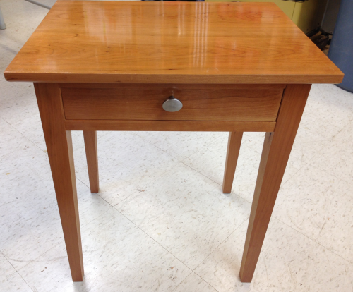
The overall look...
After the second coat of Waterlox®, I sanded with wet/dry 400x...and then third coated with Waterlox® |
 |
After prepping the drawer, I decided that I could not live with a flaw in the bottom left corner of the drawer front. This corner dipped in...to level it out I had to plane the whole side of the drawer. After the planing, the left drawer side was thinner than the right drawer side so there was some gap. |
 |
I decided to scab the sides...so I trimmed off a thin slice of cherry...about 1/32 inch. |
 |
Sawed to a fat length...then shot the ends until it fit perfect. |
 |
Dry fit for thickness...it was tight. |
 |
Glued the scabs on...then used Auriou rasps to make the fit right and sanded up to 400x. |
 |
Applied shellac and varnish...I also added a strip of UHMW polyethylene to side guides for friction reduction and to make the guides fatter. |
 |
Screwed in a stop block for the drawer. |
 |
Installed the knob. Ready for the top to be attached and final varnish rubs. |
 |
The table top was given a final planing... |
 |
...and was then sanded from 150x to 220x, 320x and 400x.
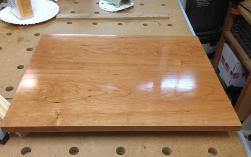
Then finished with shellac and Waterlox® as shown below. |
 |
The typical pattern for this table was rubbed on application of Super Blonde shellac, steel wool, second shellac, two coats of Waterlox® rub on varnish-oil, wet dry sandpaper 400x, rub polished with cotton cloth, third Waterlox®...here is the top at that stage. |
 |
|
To attach the top to the apron...in addition to the kicker rail, cabinetmaker's buttons were made with tenons to fit into the slots in the apron. The buttons were made from oak...the first router cut is the top edge of the tenon...this is the critical cut...it must make the top of the button co-planar with the top of the apron. |
 |
The tenon was created by flipping the oak piece to cut the bottom side of the tenon...this tenon was cut fat. Any adjustments will be to the bottom side of the tenon. |
 |
A LN small shoulder plane was used to sneak up on the perfect fit...it was planed down so that the tenon will be comfortably tight in the groove but it will allow for wood movement along the groove or in and out of the groove. |
 |
Here is the crash test dummy dry fit. |
 |
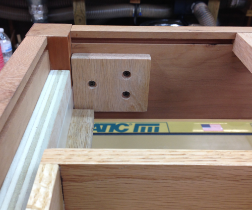
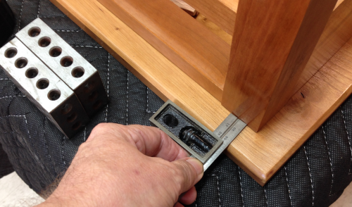
The carcase is to be secured to the underside of the tabletop with screws through the cabinetmaker's buttons. A countersink space was made with a Forstner bit...the screw is a 1 inch square drive with a shoulder. |
 |
The screw protruded ~3/8 inch...it will be screwed into a top that is 5/8 inch plus. |
 |
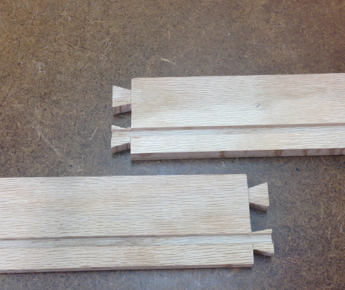
After the sizing and fit was tested, the two sticks of oak that had the tenons routed and planed to size were laid out for a dozen buttons. |
 |
The buttons then had the counter sunk holes drilled, the through holes drilled and then they were crosscut . The finished oak buttons. |
 |
The button placement will look something like this... |
 |
The top was put upside down on a blanket on the assembly table and was squared carefully... |
 |
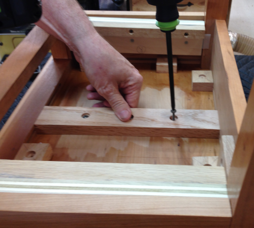
...shallow starter holes in the top were drilled through the existing hole and the kicker board was the first to be secured. |
 |
The side buttons were abandoned because the angle was too tight for screwing the buttons down. The rear buttons had some issues with the back upper edge of the drawer...similar to the issue with the kicker board. Two buttons were thinned down and installed...problem solved.
|
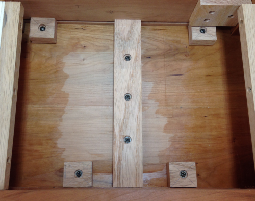 |
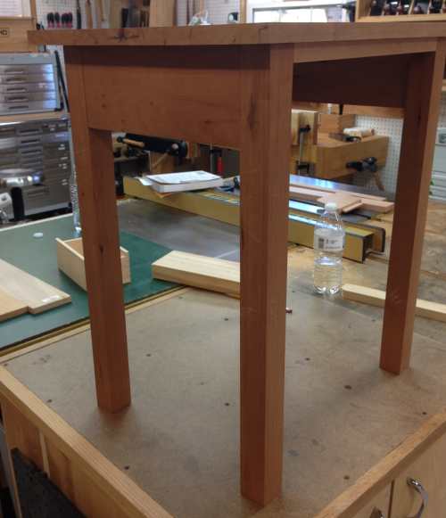
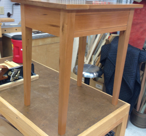
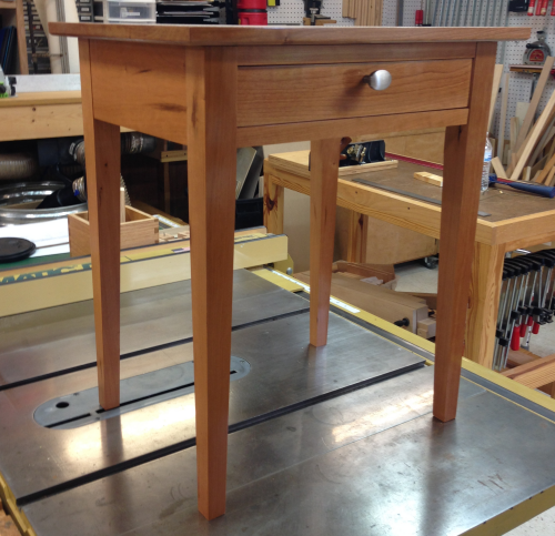
The table with the top installed. |
 |
Top secured...side view with drawer showing dovetails. |
 |
|
|
The typical pattern for this table was rubbed on application of Super Blonde shellac, steel wool, second shellac, two coats of Waterlox® rub on varnish-oil, wet dry sandpaper 400x, rub polished with cotton cloth, third Waterlox®...here is the top at that stage. |
|
Note: When the top was first coated with Waterlox® some issues with the surface became evident...these were mainly small scraps from the plane edges, a small ding, and a couple of grain tears. These were not evident when the top was first prepped...they showed a little after shellac but jumped out after the gloss of the varnish. I was unhappy so I sanded again...used the rotary all the way down to 80x and then worked up to 320x through the typical grit cycle. At the end I use 320x to hand sand in the direction of the grain to try to hide the sander squigglies. Then the whole shellac pattern and varnish pattern was applied a second time...happy with the result. |
|
The shellac and varnish protocol was rubbed onto the leg sections before the final glue up of the lower section. |
 |
Final varnish applications were done on the assembles, glued up carcase and table top. |
|