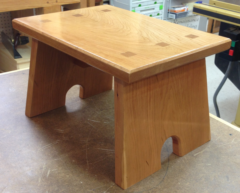
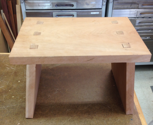
This stool is a house-warming present for my brother, Bill.
It originally was going to be a thick-style maple stool similar to the one I made for Cindy.
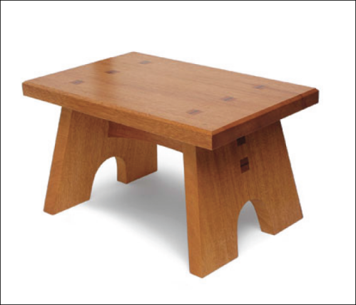
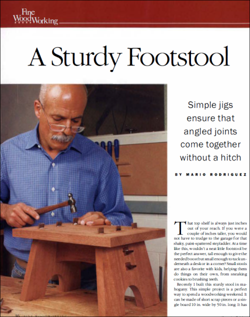
But safety issues were a concern and I decided to go with a wider and longer stool with angled legs for greater stability. I opted for a design I had liked in Fine Woodworking (January 2002)...Mario Rodriguez had created his stool in mahogany...Bill's will be made of cherry.
|
|
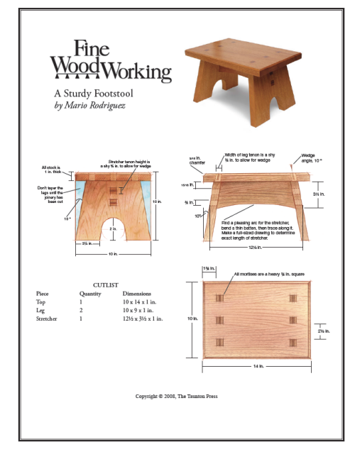
Here is a scale drawing of Rodriquez stool. |
 |
Here is the full article from Fine Woodworking. |
 |
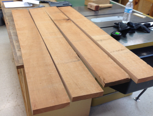
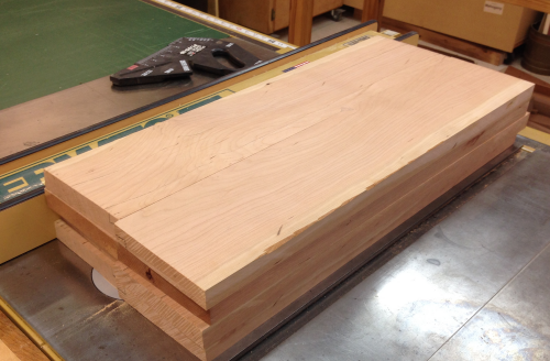
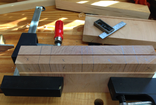
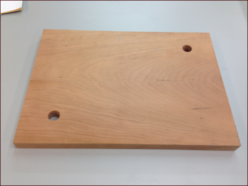
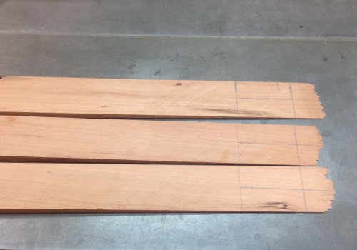
The wood for this stool was some 4/4 cherry that I have had for a long time...the wood was a bit wonky. The two pieces were 11.5 inches wide by 48 inches long. Max helped me rough rip them to ~5.5 inches on the bandsaw.
|
 |
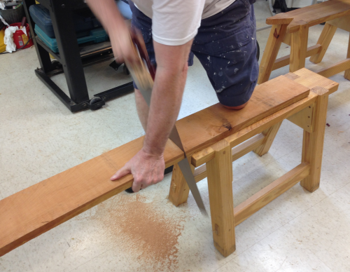
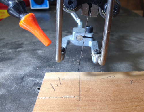
| I then crosscut them at 14 inches...because they were so wonky I cut them with a handsaw. |
 |
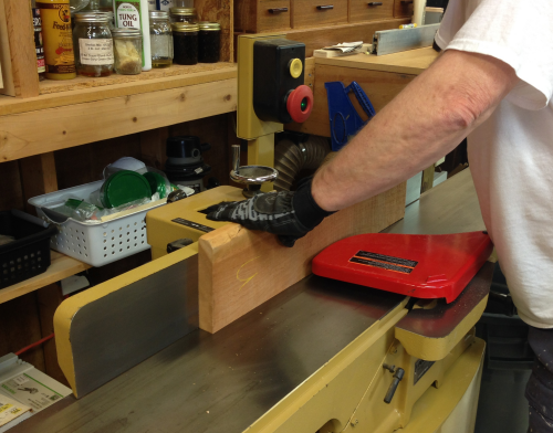
Cindy and I then ran them across the jointer to flatten a face... |
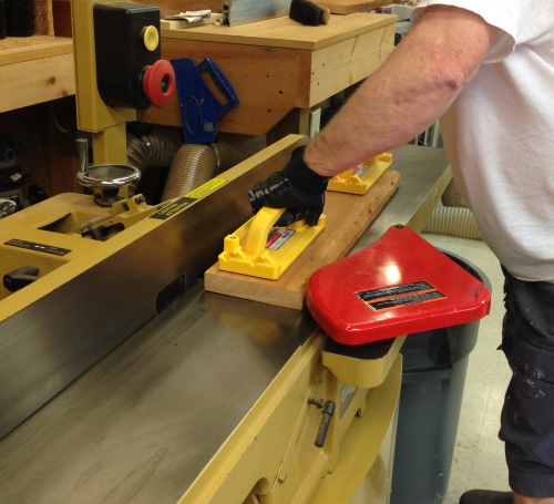 |
...and on an edge to make a square edge. |
 |
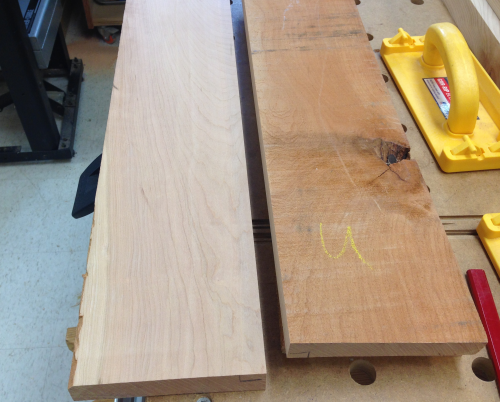
The cherry looked nice after a surface run...
|
 |
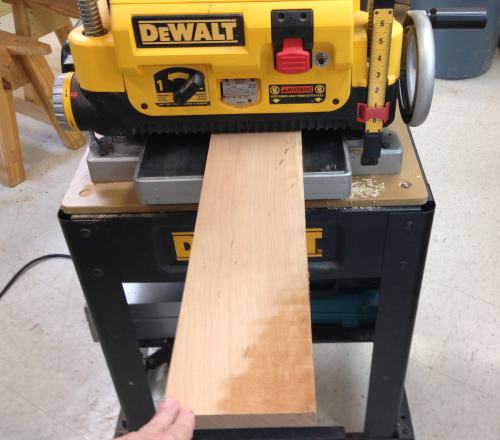
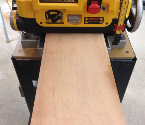
Then Cindy and I ran them through the planer...I had hope to end up with about 1 inch thick stock...but the wonky wood made us mill it thinner.
|
 |
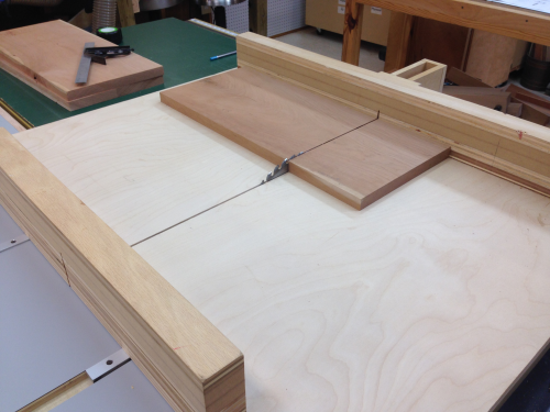
Surfaced wood is now ready to be ripped at the table saw... |
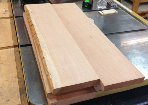 |
The wood is now about 5.25 wide. |
 |
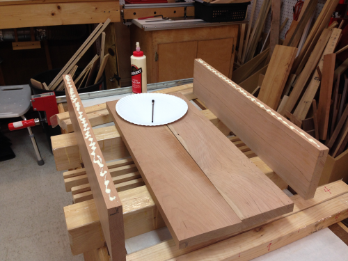
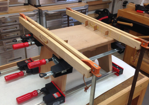
The boards were then glued edge to edge to create 10.5 panels. Here two sets will be done at once. |
 |
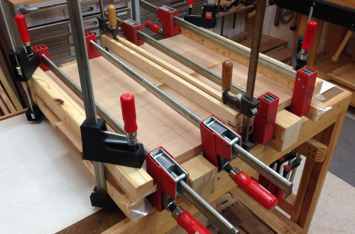
Three sets of cauls were used to hold the board coplanar...and a number of Besseys were used to hold them tight.
|
 |
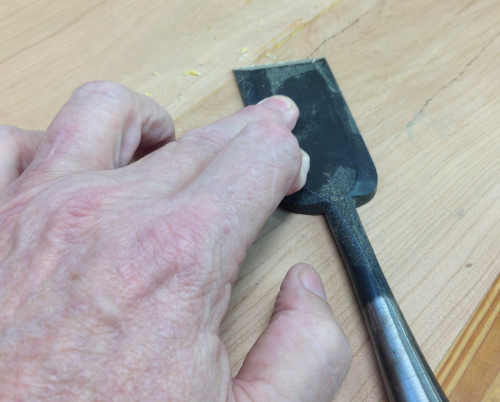
After the glue setup, excess glue was removed with the Nishiki Kinari... |
 |
...and then the glued up panels went through the planer. |
 |
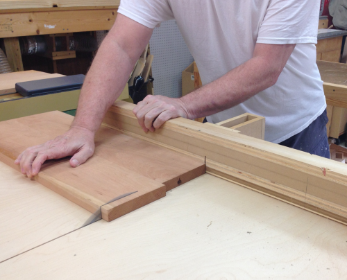
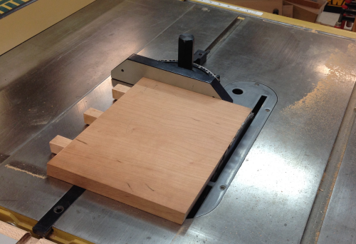
Panels were then squared using the crosscut sled on the PM66. |
 |
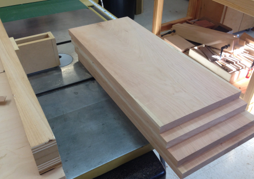
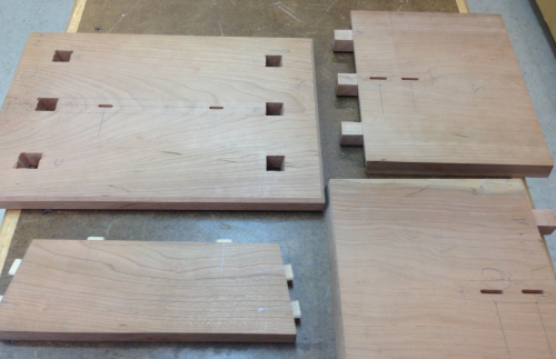
Four panels...10.5 inches by 24 inches. |
 |
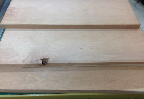
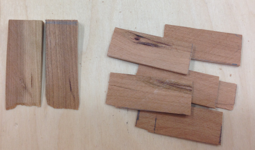
After a month the panel blanks were brought back out and assessed for flaws and wonkiness.
|
 |
Then final leg blanks and the top blank were cut to size on P66 crosscut sled. |
 |
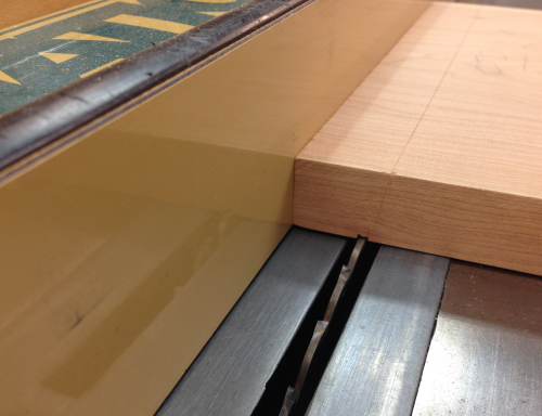
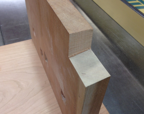
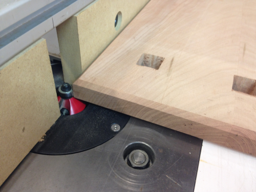
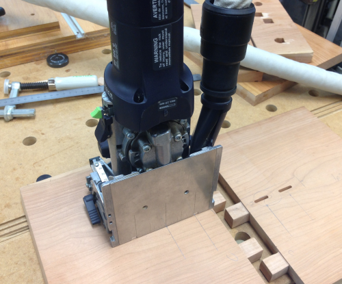
The tenons on the top of the leg need to be 3/4 inch thick. I also wanted s very shallow shoulder cut on each face, ~1/16 inch on a ten degree slant. This will make the underneath tenon/mortise fit look better. Here is one face cut at 10° on the P66 with Tenryu blade. |
 |
I then moved the fence to the other side of the blade and cut the other angled shoulder. |
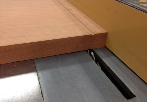 |
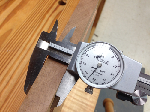
I then switched PM66 to Infinity 1/4 inch flat top blade. After a few runs on the crash test tummy I got the depth of cut to ~1/16 that once cut and then flipped gave a result of ~3/4 inch. I wanted it a little fat and got .005 inch over the .750... |
 |
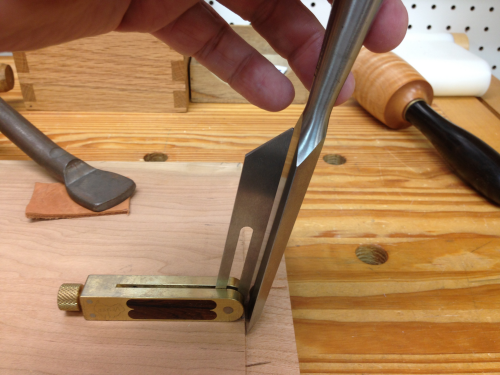
To make the shoulder joint edge look good I tapped the edge at 10° with a chisel... |
 |
After paring the tenon cheek back into the angle the tenon looked pretty clean. The other side will be cleaned up with a chisel jig. |
 |
Using a 10° jig and then paring the cheeks I finished the other side... |
 |
...both sides cleaned. |
 |
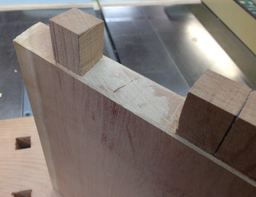
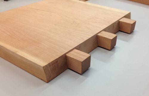
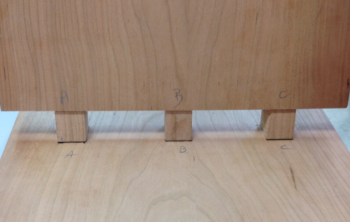
To be able to visualize the tenon locations I made a story board and transferred the locations to a leg. |
 |
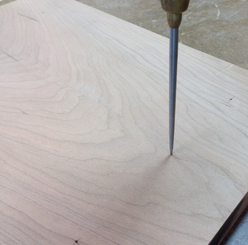
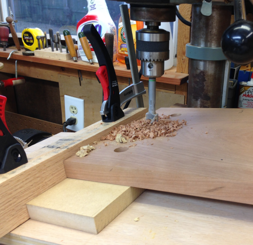
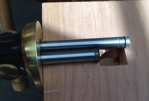
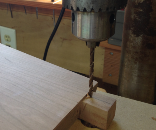
I used the story board to locate the mortises on a CrashTestDummy top. I then drilled 10° holes into the mortise locations using the new angle jig on the drill press. One of the things that I learned from the CTD was that drawing out the mortise squares was useless... |
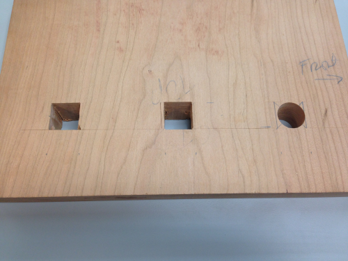 |
...it was better to just have a center point. |
 |
I had also learned that I could not drill all three holes without realigning the jig...so I started by reversing the jig to slant up right to left...and drilled the far hole. I used a Zobo Forstner bit with an extended center point to make it easier to hit the center. |
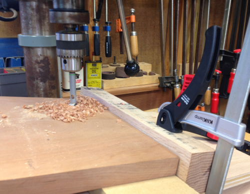 |
Top after the first two holes... |
 |
Then the jig was set to rise left to right and the final holes were drilled. |
 |
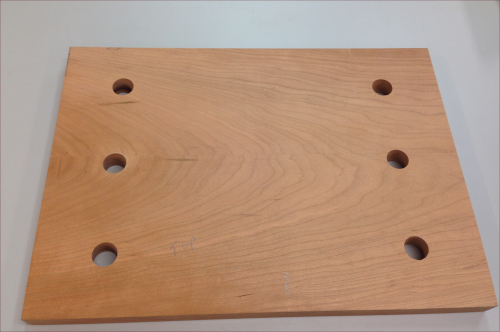
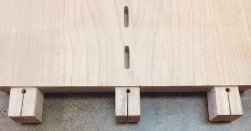
All six holes... |
 |
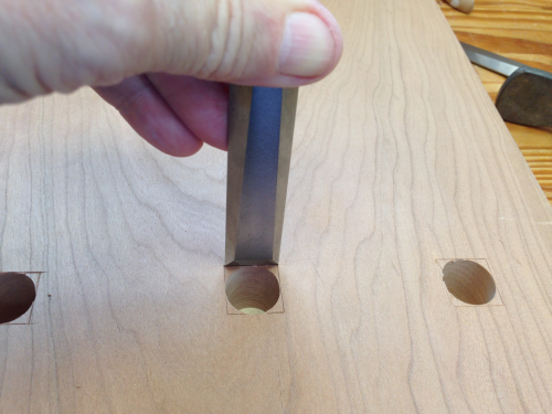
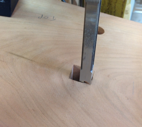
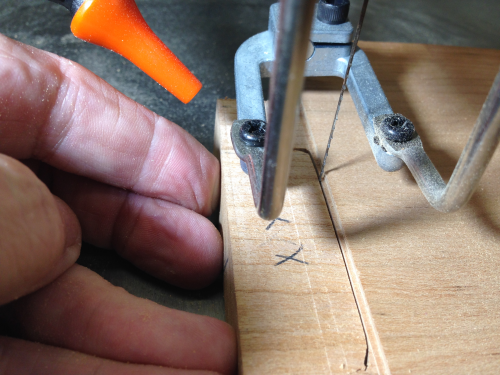
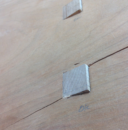
Then using marking gauges and marking knives I marked off the square around each drilled hole. |
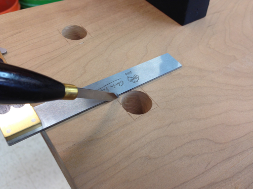 |
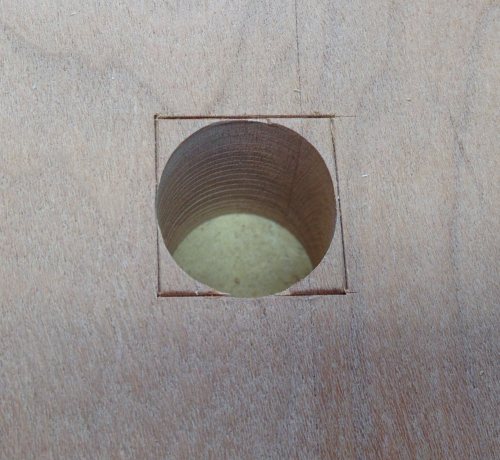
Then used a 3/4 inch chisel to more clearly define each mortise edge... |
 |
...result... |
 |
...and then set up an angled jig to guide the chisels to take out the mortise edges. |
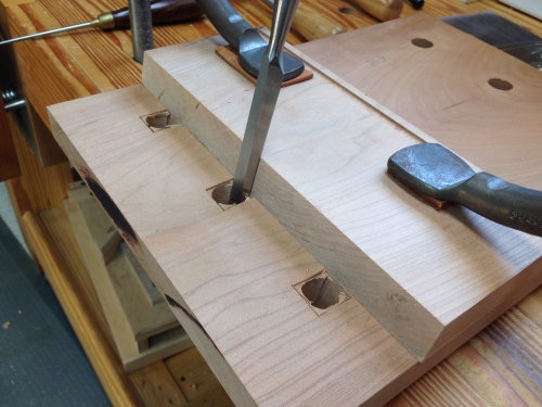 |
This method was somewhat long and tedious...and in particular there was problems on the backside... |
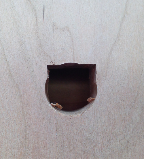 |
To define the mortise edges on the backside I measured off of the sides of the top and marked these edges out on the backside. |
 |
I opted to make a jig that would let me make 10° mortises on the PM desktop mortiser . This enabled me to make nice clean cuts at the top but the backside still had some issues. |
 |
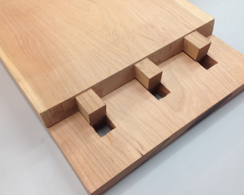
After getting all of the slanted mortises into reasonable shape, I tested them with a 3/4 x 3/4 inch oak CTD tenon that was hammered through all of the mortises. |
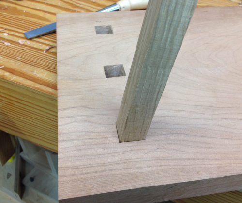 |
The original tenon markings were eliminated and new ones were made from the mortises. |
 |
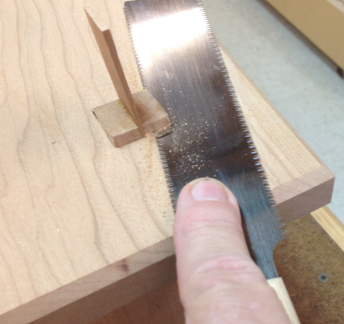
The rip cuts on the tenons were cut with the Bad Axe Stilleto. |
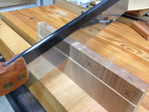 |
The crosscut on the shoulder was cut on 10° using the Bad Axe small tenon saw. |
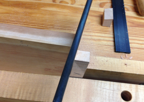 |
Waste was removed with the scroll saw. |
 |
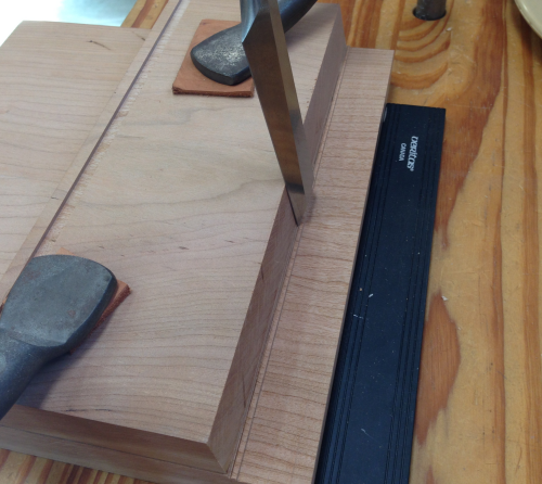
The angled shoulder was pared... |
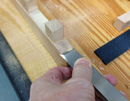 |
...and checked for the angle. |
 |
I tried out cutting an angle with the Jet scroll saw. Set at 10° I tried the cut on a CTD. |
 |
It turned out well... |
 |
So I used the 10° slant cut to remove the waste between tenons and a leg. |
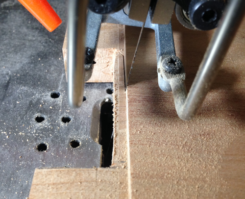 |
This turned out really well...a little paring and all was well...the only problem had been getting a starting point with the scroll blade. |
 |
So I made another rip saw cut and removed a portion of the waste so that it would be easier to start the scroll cut. |
 |
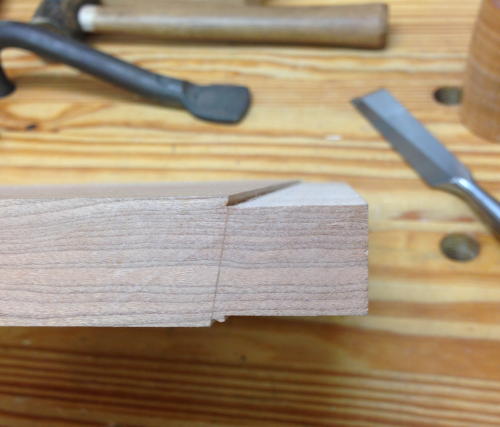
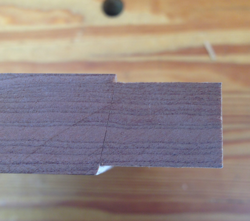
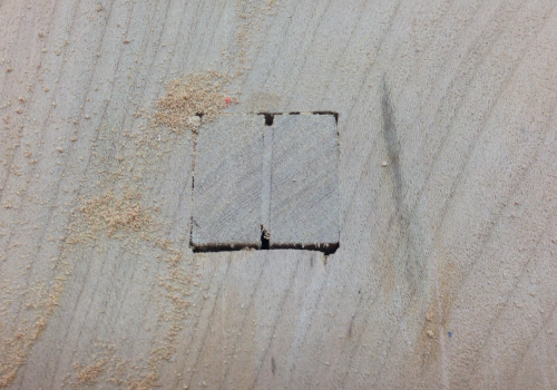
A finished 10° shoulder line with tenons. |
 |
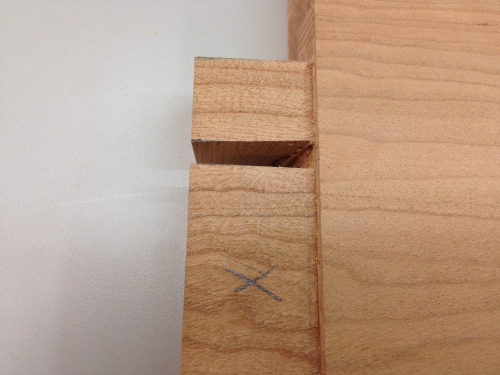
The tenons were all a little fat, so they were matched up with the mortises and faces were then worked with rasps and sandpaper.
|
 |
A series of dry fits showed where to work. All went well till the very end...I lost my patience and tried to fully seat the leg...a tap too far with the joinery hammer and... |
 |
wham...a disaster...a crack along a a grain line. A lot more work to do...
|
 |
Finished the tenons and mortises... |
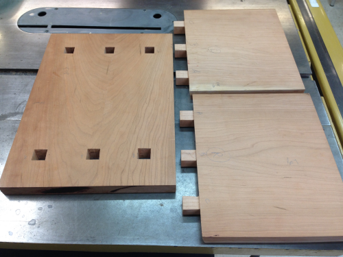 |
Dry fit |
 |
Time to start making the legs fit right...a crosscut at 10° for the angle on the bottom of the leg. |
 |
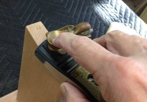
The top was bevelled at router table with 45° chamfer...top and bottom edges. |
 |
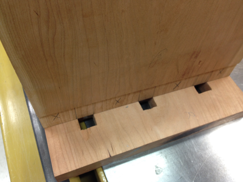
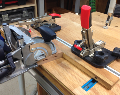
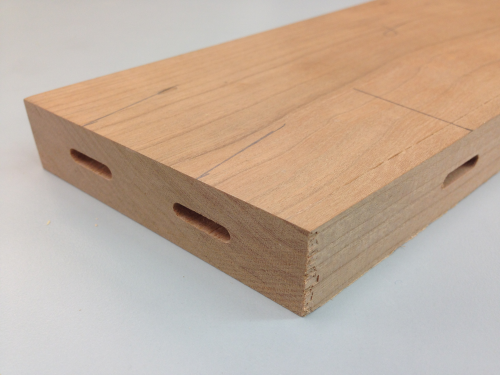
A plywood model for stretcher was made to test the fit...I opted to use Domino floating tenons rather than attempting through mortise and tenons. |
 |
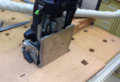
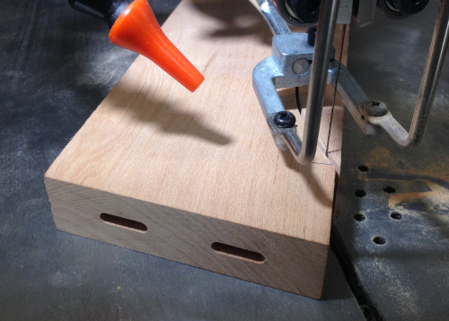
The thickness of the stretcher blank meant that placing the Dominoes exactly in the center of the wood with the nominal mm Festool settings was going to be difficult. So, I placed the setting to be close to center...and made all of the mortises (tight) based on one reference face... |
 |
...and then planed the opposite face until the mortises were centered. |
 |
The stretcher was then centered in the stool... |
 |
And all of the mortise layout lines were extended to the bottom side of the top and the inside faces of the legs. |
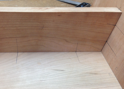 |
The edges of the stretcher were marked onto the other surfaces and then center lines were created in those areas. The Festool was then used to place tight mortises on those center lines in the top. |
 |
On the legs the mortises were made in the middle loose range and centered. |
 |
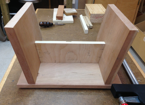
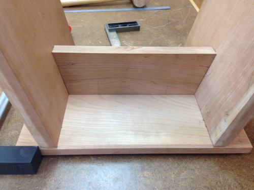
Finished pieces ready for final dry fit... |
 |
...which had to go very slowly due to angled surfaces... |
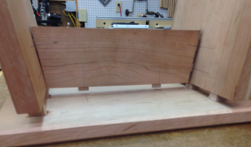 |
...and then were tapped... |
 |
...until seated. |
 |
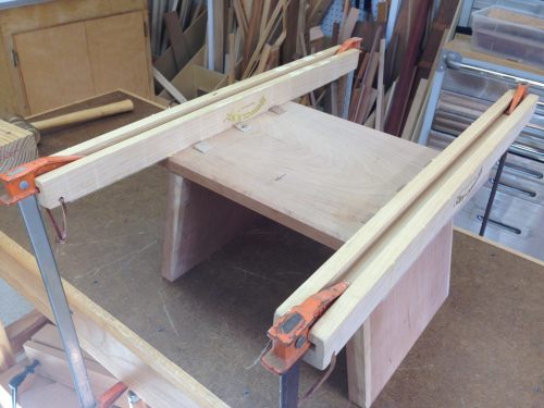
While the stool was assembled in the dry fit, I took the opportunity to check out possibilities for clamping angles. Bessey's on the top and bottom of the legs should close gaps around the ends of the stretcher. |
 |
A couple of Bowclamp cauls and some F style clamps will hold the top down. |
 |
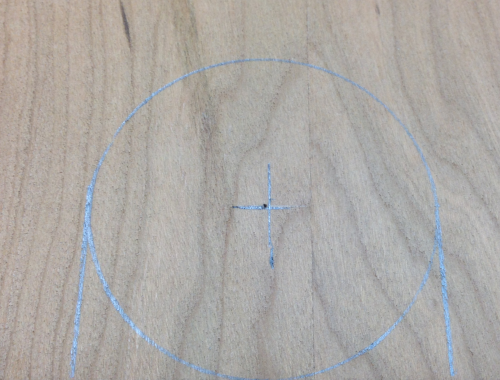
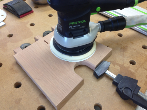
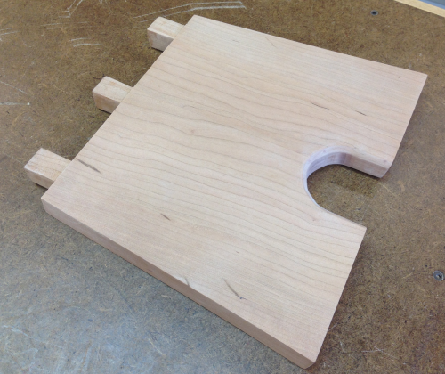
The legs needed cut outs and the angled edges. A two inch circle was centered...
|
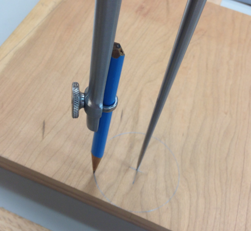 |
...and the edges were extended. |
 |
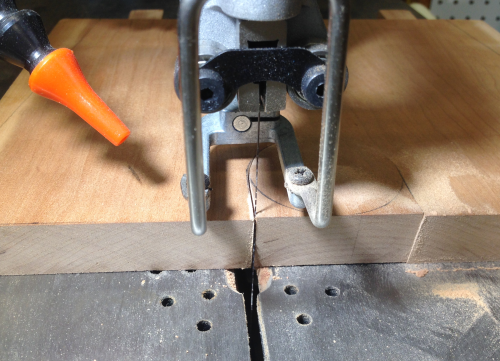
The cut was made on the Jet scroll saw. |
 |
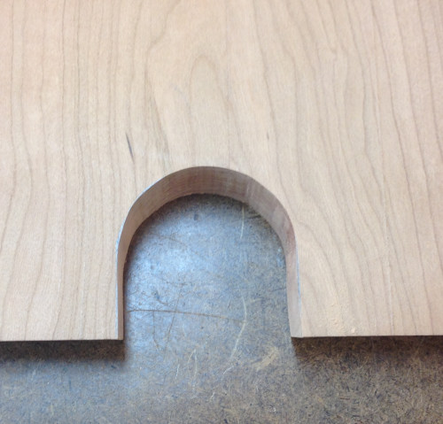
Result... |
 |
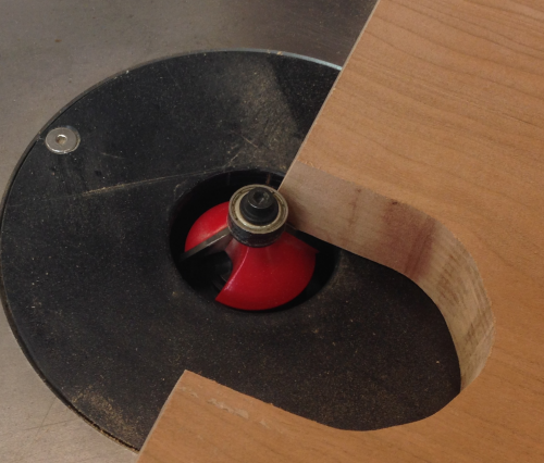
...and then the edges were 45° chamfered on the router table. |
 |
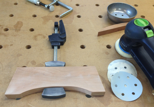
After the angle cuts were made at MFT3 table the legs were rotary sanded...100x, 220x, 320x and 400x. |
 |
With some 400x and 800x hand sanding to put a small radius on edges...leg assemblies are ready. |
 |
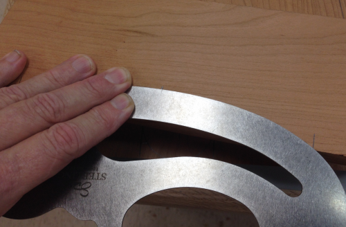
The bottom edge of the stretcher was to get a curved relief...laid out with French curve. |
 |
Cut out on Jet scroll... |
 |
DX90 sanded 100x, 220x, 400x. |
 |
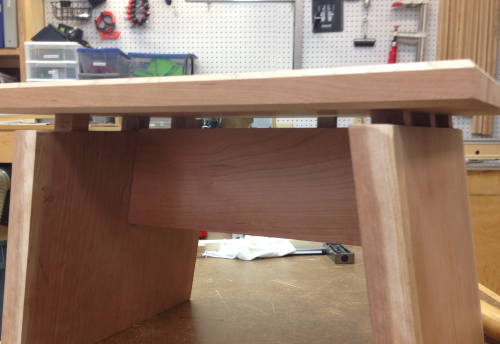
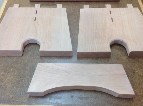
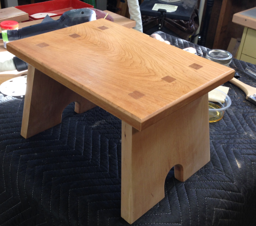
Legs, stretcher and the bottom of the top plate are all ready for assembly.
|
 |
Tenons got a 9/64 relief hole and a saw kerf to receive the wedges... |
 |
...ready for wedges. |
 |
Some cherry cutoffs from the earlie side table project provided some ready made wedges. We calculated the optimal wedge length and thickness and then cut them on scroll saw. |
 |
Six wedges along with a couple of overly thick back ups just in case. |
 |
Cindy worked with me on the glue up phase...glue was applied to the floating mortise and tenon joints, the edge faces of the stretcher, all shoulders on the legs, and the outside of the through tenons. |
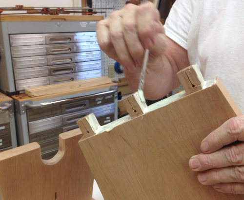 |
The stretcher Dominoes and the through tenons on the two sides were worked by hand into all mortises. Once they were all seated, the stool was turned over... |
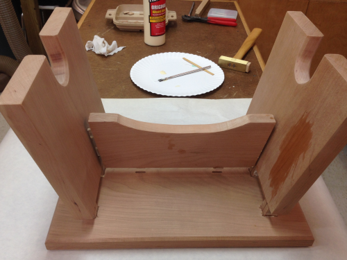 |
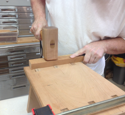
...and the top was malleted down. |
 |
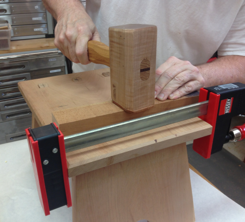
The repaired crack was held tight with a clamp during the beat down... |
 |
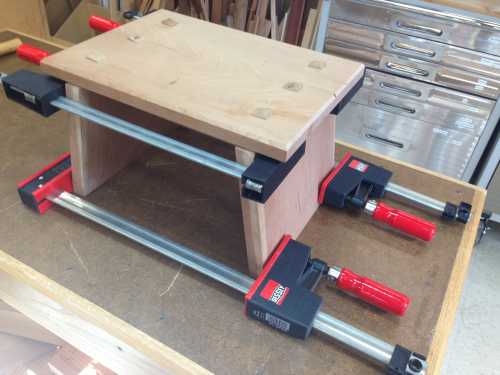
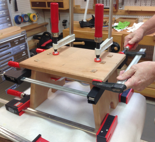
The stretcher had to pulled tightly to the top using deep throated clamps...the bessey clamps held the leg assemblies to the stretcher. |
 |
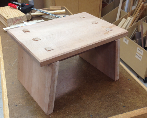
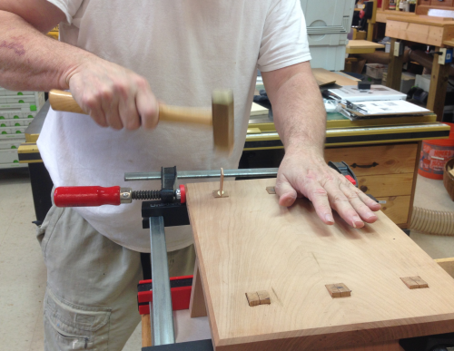
Then the wedges were glued and tapped into place... |
 |
After all six wedges were in the top was held down using the cauls. |
 |
After pulling the clamps, the wedges and through tenons were cut off flush-cut saw. |
 |
Four of the tenons were pretty nice fits...of the two poor fits, this one was the worst...used the saw dust to mix with a little glue and filled the gaps. |
 |
After checking the unit for level...there was a slight wobble...marked the high leg edges and planned them till wobble was gone... |
 |
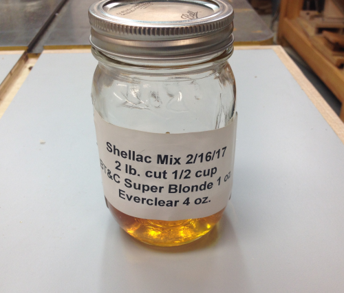
Much of the lower surfaces were sanded before assembly...did some Timbermate® work and sanded again with rotary and by hand...same for top and then applied a new mixed Super Blond Shellac 2 lb. cut...my first mix with Everclear 190 proof. |
 |
Two coats of Super Blond went on...triple ought rub downs... |
 |
Then the first coat of Waterlox® wiping varnish. |
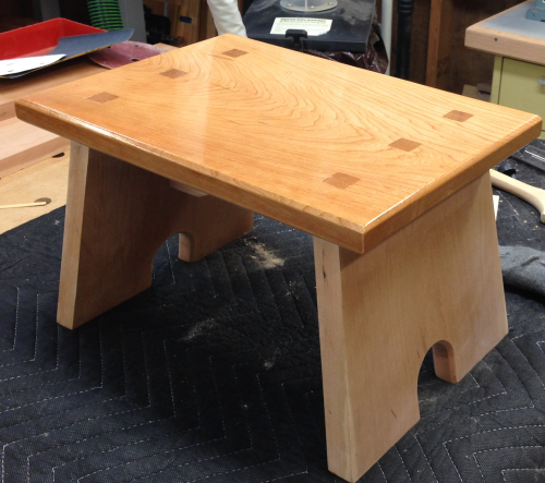 |
The shellac and varnish really pops the cherry. The top ultimately got four coats... |
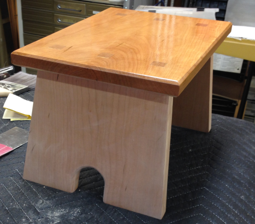 |
After two coats of shellac and two coats of varnish on the legs... |
 |