| Screen Porch Project Cindy and I decided to screen in a section of the back porch. This will involve screening in three sections and installing two doors. The longest section is the west wall...referenced as "the wall"...approximately 13 feet of opening with an open height of about 90 inches from the concrete slab to the frieze beam. There will be a screen door in this wall. The opening, facing north, above the brick porch skirt and between the brick columns is referenced as "the window"...it is ~140 inches wide and ~60 inches high...extending from the top of the brick wall up to the frieze beam. The final section connects a brick column to the corner of the breakfast area extension...it is references as "the doorway". The width will be about 7 feet with a height of about 101 inches...this opening extends from the concret porch slab to the plywood ceiling. The screen door builds are shown here.
|
|
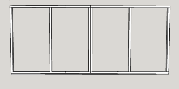
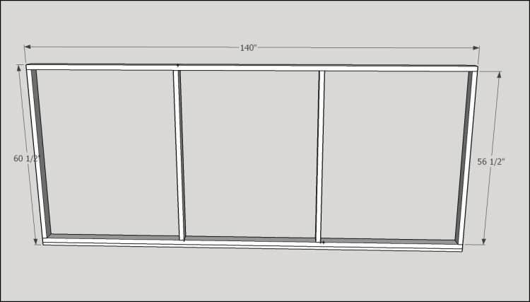
The window will be the first section to be built and installed. First sketchup plan... Composit plank sill plate to run the entire width. Wall frame of treated 2x material to run the entire width and height. Rebates in the frame to hold screen frames made of extruded aluminum.
|
|
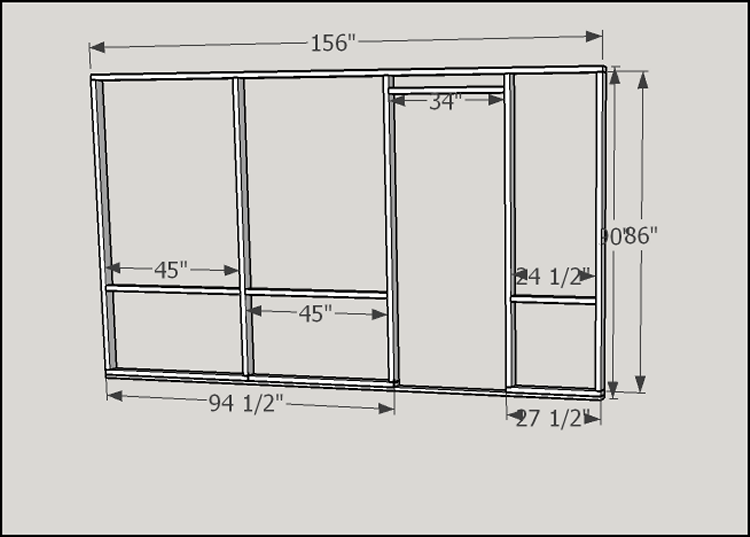
After some deliberation...in an effort to reduce the size and weight of individual sections...the design was changed to this... Composit plank sill plate to run the entire width. Wall frame of treated 2x material to be created in two sections ~70 inches wide...there will now be four frames instead of three.
|
|
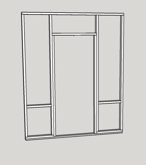
The wall will be the largest section to be built and installed. First sketchup plan... Composit plank sill plate to run the entire width. Wall frame of treated 2x material to run the entire width and height, plus a door frame. Rebates in the frame to hold screen frames made of extruded aluminum.
|
|
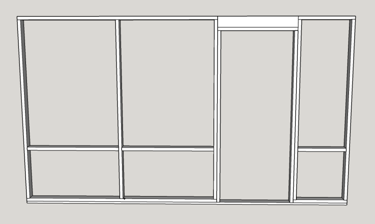
Second sketchup plan... Composit plank sill plate to run the entire width. One wall frame, ~8 feet long that will end at the doorway, a small wall frame to the right of the doorway, plus a door frame. Rebates in the frame to hold screen frames made of extruded aluminum.
|
|
|
The Doorway |
|
Original plan for the doorway... |
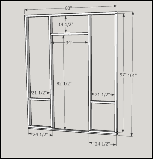 |
Reconsideration...second plan for the doorway... ...door frame change. |
 |
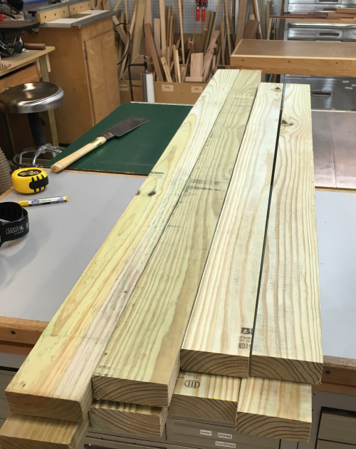
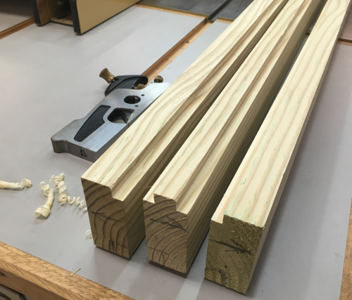
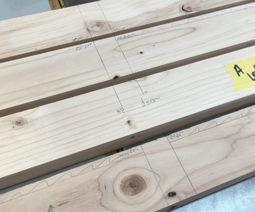
Treated pine will be the lumber used in all of the wall framing... ...typically I selected wider boards because the choices at the BORG were better and drier wood. For the window, the 2 x 8 x 12 treated wood was cross cut ripped to rough dimensions. |
 |
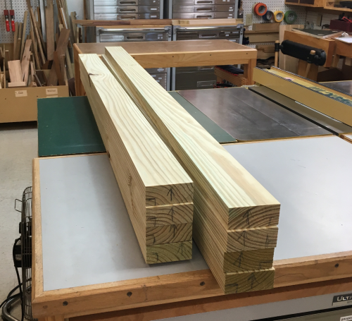
Then the best face was jointed and the rip face was jointed...providing a square edge. Then surface planed and ripped at P66 to provide blanks of 1 5/16 thick by 3 1/4 inch wide. These blanks will allow some de-wonk time and will be milled again as needed. |
 |
Ater a time, selected stock for two plates and three stiles. Nominal size 1 3/8" thick and 3 1/8" wide...marked out for milling... |
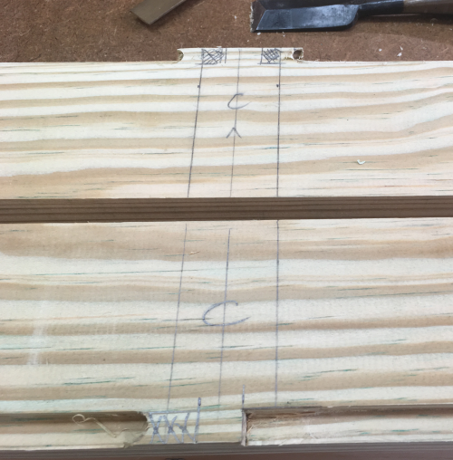 |
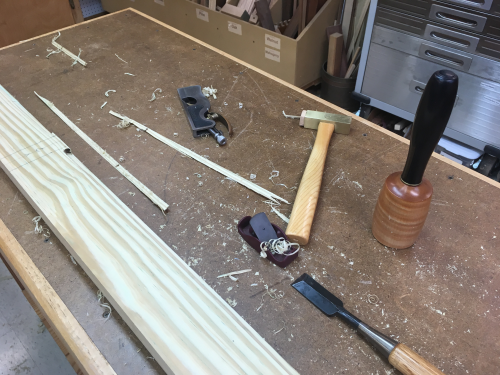
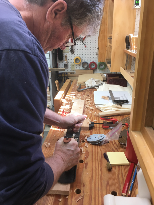
the stiles all got a vertical rebate 3/8 x 3/8...through rebates were passed over 3/8' Whiteside up/down cut bit in the router table... ...in most place the LV was the tool. |
 |
Some wonky spots required multiple planes and chisels to get it right. Really liked the Little Victor clone.
|
 |
The top plate and the bottom plate had to have stopped rebates milled...dropped onto and pulled out of the bit at the router table. |
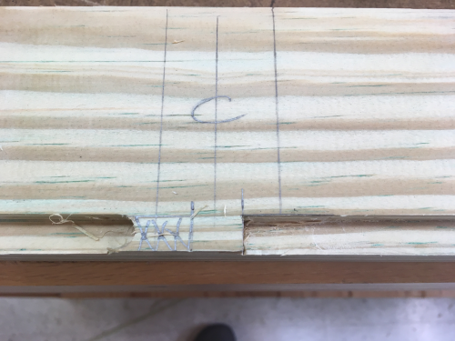 |
And then chiseled out remaining waste... |
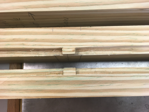 |
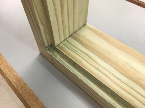
The rebate corner joints in alignment... |
 |
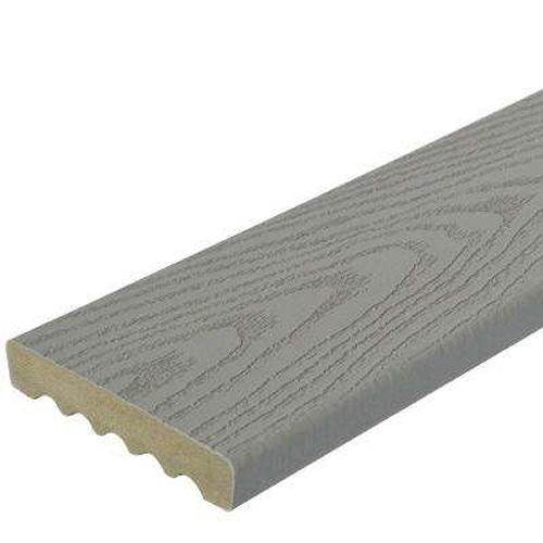
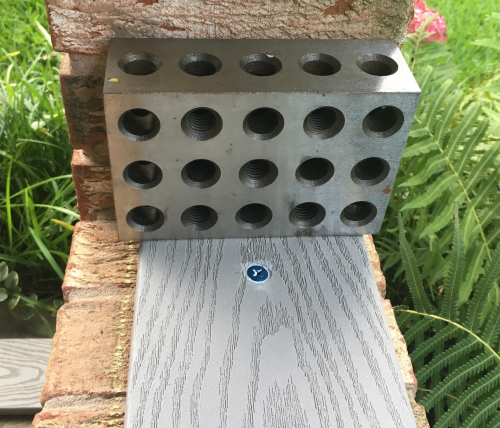
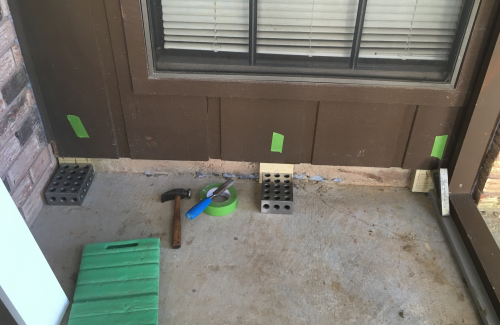
The sill plate for each of the sections is a composite board. The Veranda deck material was purchases at the organge BORG...this material is one inch thick by 5 1/4 inch wide. |
 |
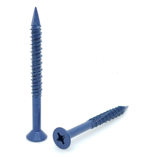
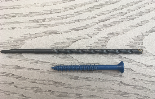
To anchor the sill plate...used SNUG fasteners (SNG495) 1/4" x 2-3/4" flat head Phillips diamond tip. |
 |
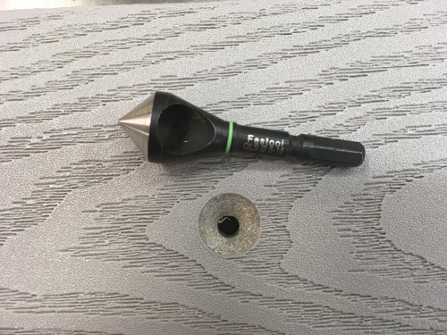
Holes for the anchor screws
were drilled at 1/4 inch and then were countersunk. |
 |
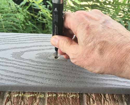
To mark the location of the holes in the brick...used a FastCap long tip pen that would reach through the 1 inch material... |
 |
Used the masonry bit that came with fasteners, ~7/32 inch. |
 |
Marked the sill plate locations
with chalk, marked the through holes with the long tipped pen. |
 |
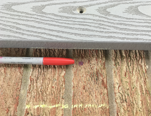
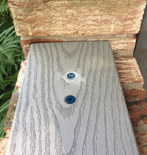
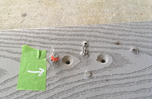
Came back and marked the spot
with a red dot...easier to see... |
 |
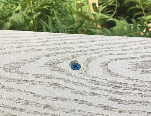
Drilled the holes with a 13/64
masonry bit and 1/2 Makita hammer drill...installed the five screws...the
middle three were great. |
 |
The two end screws had holes that went into the masonry...did not hold well...tried to redo with some caulk...not tight. |
 |
So drilled new pilot holes, reamed with countersink and did the masonry drill...the second screws held well. |
 |
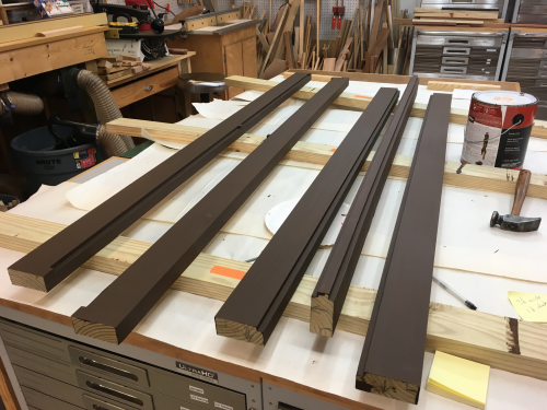
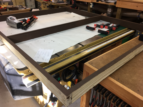
Prepped the wall plates (top & bottom) and the stiles and painted them. |
 |
Final dry fit and measure...two plates on the sill and real world measurement to the upper beam Measured at left, center and right, inside and outside edges. Trimmed stile in 1/8 inch increments until it was satifsfactory at all points...cut all three stiles to that length. |
 |
Nailed the bottom plate to
stiles...screwed the top plate...in the event there were issues with
the fit. |
 |
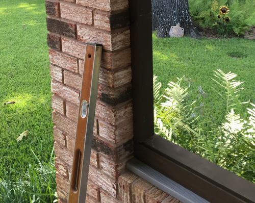
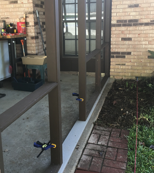
Dry fit of first frame...Positioned the frame reasonably level in both planes.
Put 2 inch deck screws into sill plate...2 1/2 inch deck screws into the overhead beam. |
 |
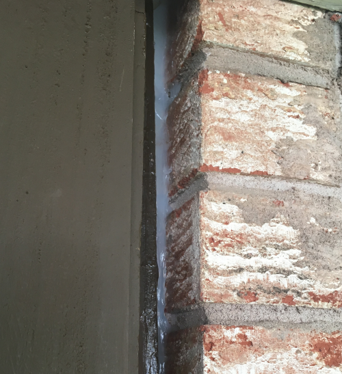
Inside and out, any surface
that connected with brick was given a silicone caulk seal. |
 |
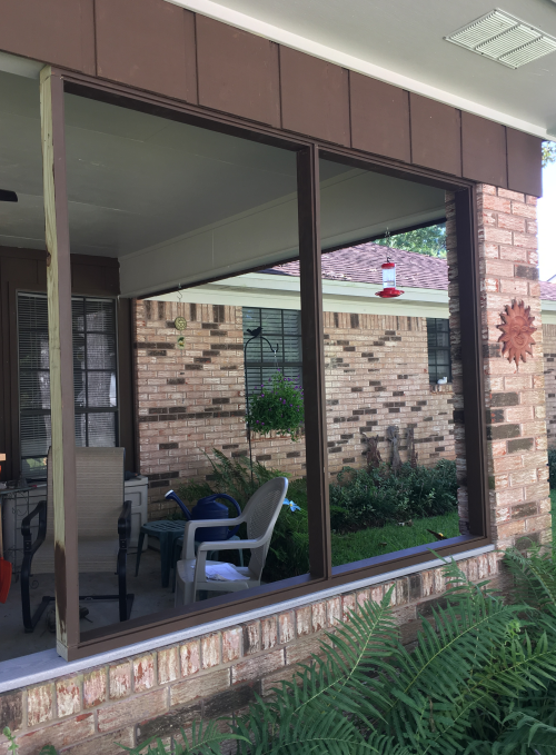
Finished Windows area... |
|
|
"The Inner Doorway Section"
|
|
Second section to work on was
the doorway (Inner Section)...the process of drilling holes for the
concrete screws was a total failure in the hard concrete slab...we had
to go to a powder actuated tool...using a hammer ramset with yellow
powder rounds failed...borrowed a trigger ramset and bought red power
rounds...it was still a hit or miss proposition. |
 |
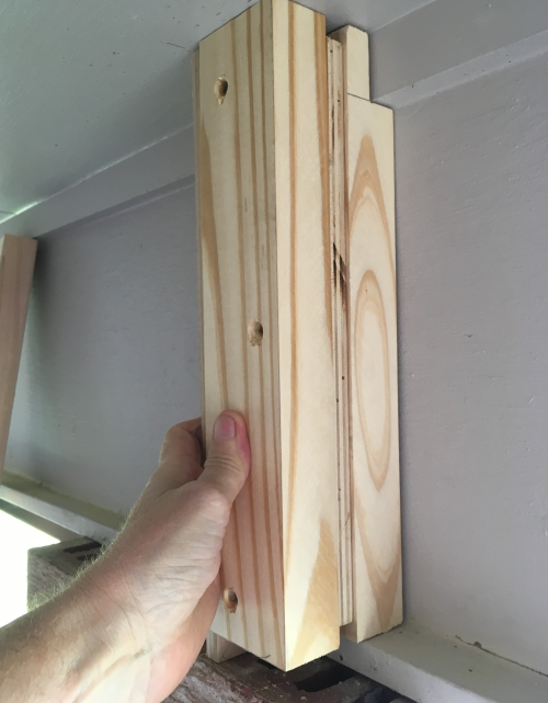
Decided to put in an vertical
anchor on each end of the sill plate...on the end toward the house we
had to scab on an end plate anyway...tried a 4 x 4...too difficult...instead
created three scab boards...the triplets. |
 |
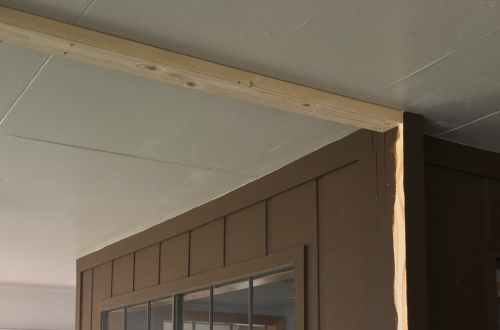
At the other end we scabbed a section at the top above the brick pillar so we had a good fixed point... |
 |
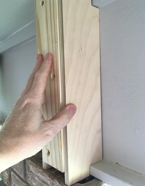
A cover piece of plywood will hide the edges... |
 |
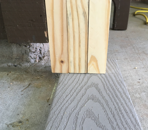
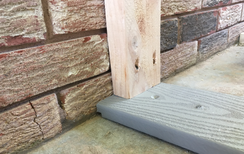
...and then installed the vertical end board...the singleton. Note the 3/8 x 3/8 routed weep hole in the sole plate. This is for water flow.
|
 |
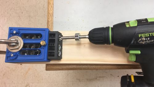
Next was a ceiling plate that
connected at each end with pocket screws... |
 |
...and also midboard with screws into the only ceiling support available. |
 |
The layout for the rebates on the frame in the doorway was a bit complicated...this was due to long stiles and the need for stopped rebates... |
 |
| Installed frame with dry fit of screen door... | |
Threshold... |
|
| Finished doorway section | |
|
"The Big Wall"
|
|
The A section went into the corner of the big wall where it meets the brick. Scabbed couple of pieces in the corner...painted dark brown Caulked silicone into brick connection. |
 |
In the back corner...scabs were installed... |
 |
| A board was put in at the bottom...painted. | |
All frames in and painted... |
 |
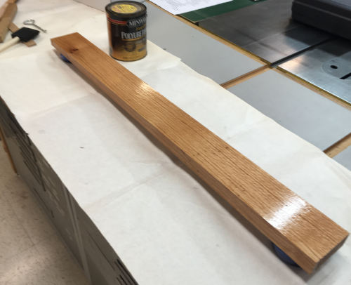
Threshold had to be cut on a bias to enable a resonably level surface...wood was planed by hand and jointed at PM. |
 |
The west threshold is weather exposed...the bottom and top surfaces of the threshold were multi-coated with polyurethane. |
 |
| Door installed... | |
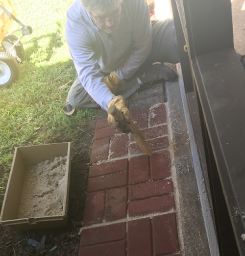
Dealing with splash up...this wall area has two different roof lines dropping water...we removed about twenty inches of heavy fern and ground cover to extend an area of 16 x 16 pavers along the entire run of the porch slab. |
|
This required much root removal and lots of leveling... |
 |
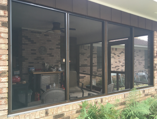
| Screen install finished | |
| Final Wall section | |
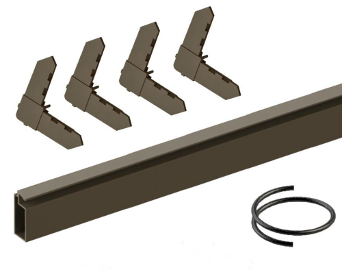
Screen frames were built with extruded aluminum 5/16 x 3/8. Kit also includes corners and spline. |
 |
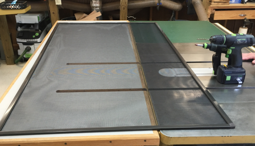
We cut the frames at chop saw, installed the 3/4 x 3/4 corner pieces which square up the frame...assembly was in the shop. |
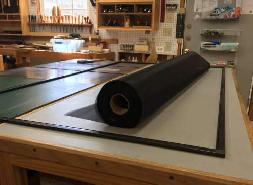 |
A finished frame... |
 |
Installed frames in the rebates with square drive round head screws. |
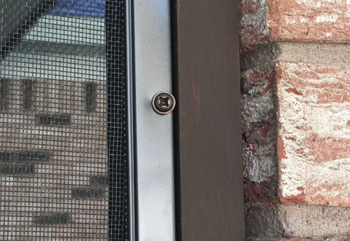 |
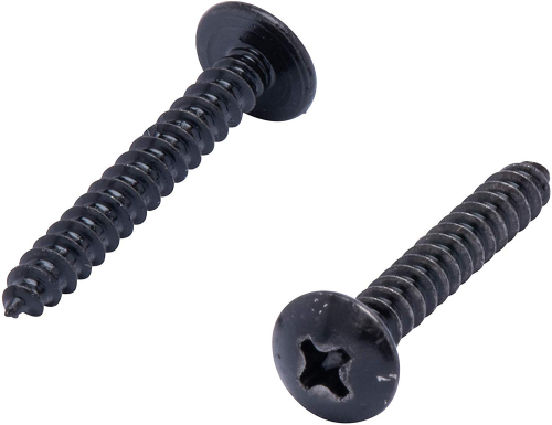
The screws started showing weathering within a day...we then tried silver stainless steel pan heads and they looked horrible...the final screw option was #6 x 3/4 stainless truss head screw...stainless steel with a black xyland coating. |
 |
First installed screen frame. |
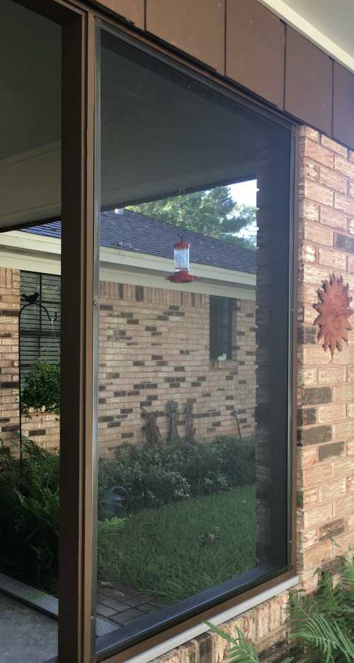 |
The window section |
 |
The west wall... |
|
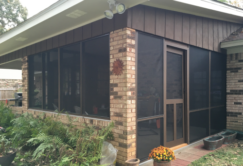
The wrap around look...the window section and the west wall. |
 |
The east doorway section... |
|
The west wall section... |
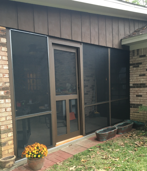 |
The west door exterior... |
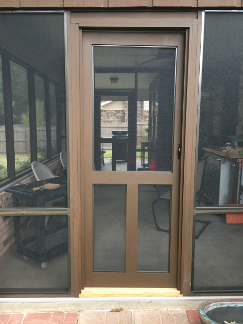 |
| east door | |