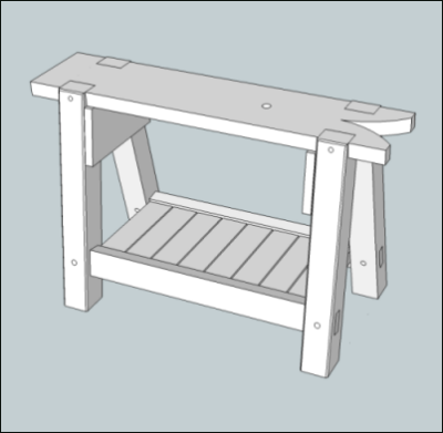
I needed a couple of sawbenches. I decided to use a traditional sawbench design.
Sketchup for the sawbench.
|
|
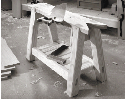
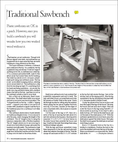
James and I looked around and really liked a design that Christopher Schwarz talked about in a 2006 Woodworking Magazine article.
|
 |
 |
|
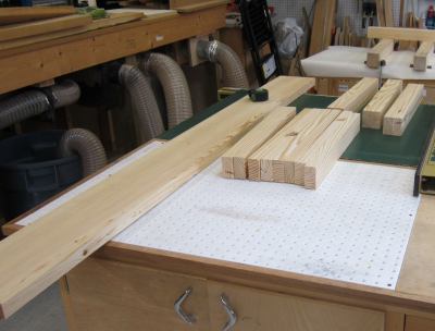
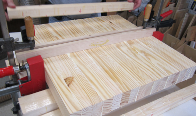
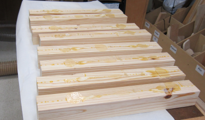
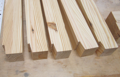
Wood for the sawbenches will be yellow pine left over from the workbench project. The 1 1/2" pine was milled down to 1 1/4 inches. All parts will be either 1.25 or 2.5 inches. |
 |
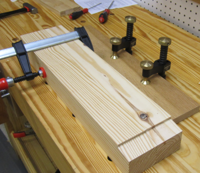
Each leg required two blanks (1.25) to be
glued together to produce the 2.5 inch legs...this was done by placing
the pieces on to the glue bases on the assembly table. |
 |
The sixteen units had glue between the proper
8 faces; then cauls were put in place to hold them all in the same horizontal
plane. |
 |
Both commercial cauls and shop
built cauls were used. |
 |
Bessey clamps were then used to provide the final pressure points.
|
 |
After overnight glue-up, the eight legs were removed from the clamps. Hand scraping removed the large glue beads. |
 |
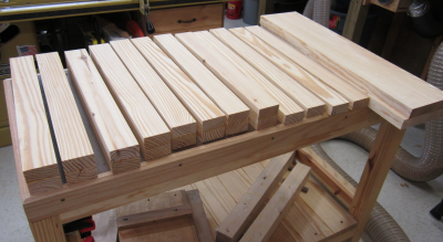
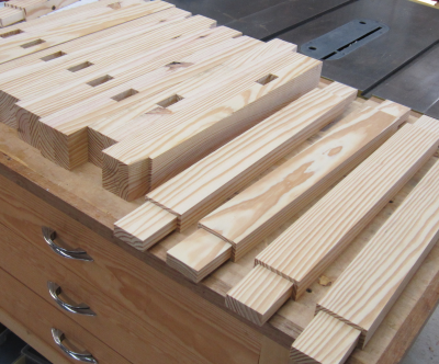
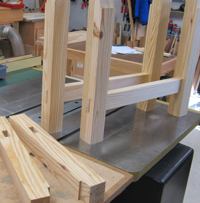
Then the legs were jointed and planed to final shape. Image shows the eight legs, four stretchers and two tops...all milled and ready for joinery process. |
 |
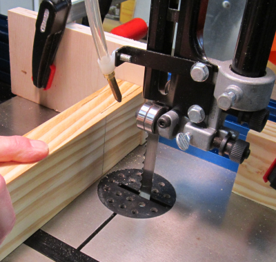
First step was to create the angled notch that will form the joint between the top of the legs and the sawbench top. This will be a ten degree angled notch. To simplify the cuts a jig was made for the bandsaw that would hold the leg at the 10° angle. |
 |
Here a leg blank is placed in the jig notch
and properly lined up for the cut. |
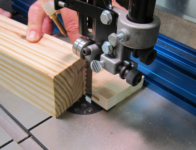 |
Because this is not a through cut, a stop block was positioned so that the cut would end in proper location and the leg could be withdrawn from the jig.
|
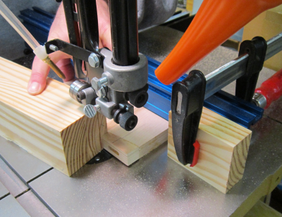 |
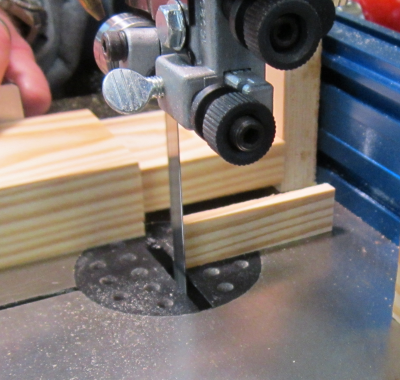
The rough cut angled notches. |
 |
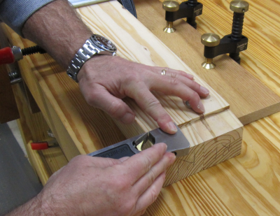
The eight legs were then divided into pairs. The two legs from any one side would then be worked as one unit so that they would be the same. Here a pair are clamped to the workbench. The slanted faces were touched up with block planes as needed to provide the proper flat surface. |
 |
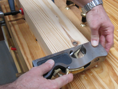
Then a shoulder plane was laid on the slanted face and used to make the notch square to the slanted surface and make sure that the notches were co-planar across the two legs. The small LN shoulder plane seemed to be the perfect fit for the job. |
 |
However, it turned out that using the large
LN shoulder plane was actually more effective and easier to control
than the small plane. |
 |
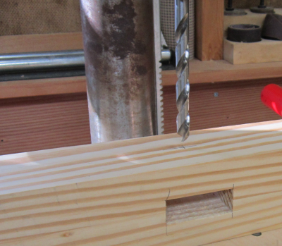
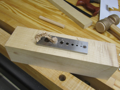
Next step was to cut the eight mortises that will connect the legs and the stretchers. Due to thickness of the leg, a layout was made on both sides...then the mortise outline was made with the Powermatic benchtop mortiser. |
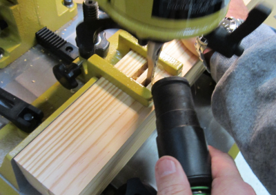 |
| This mortise work was done from both sides and the center piece then removed. | 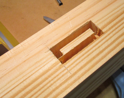 |
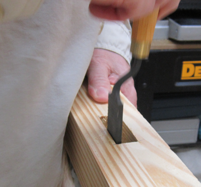
The edges and corners of the mortise were
cleaned up with Japanese paring chisels. |
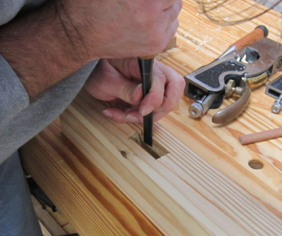 |
The sides of the mortises were touched up
with LN float. |
 |
Here are the legs with angled notches and mortises finished. On the bottom of the right leg in the image shown you can see the layout line that will be the 10° cutoff point for the bottom of the leg.
|
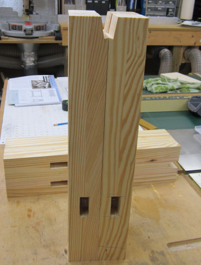 |
We decided to cut the tenons on the bandsaw.
A stop block was clamped to the fence to make the cuts consistent. |
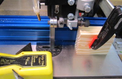 |
Had to keep vacumn steady to avoid build up between the workpiece and the stop. Should have chamfered the block for dust relief. |
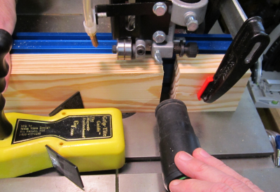 |
Finished with rip cuts. |
 |
Crosscuts were made with mitre gauge. |
 |
The Powermatic really made great cuts with
a newly installed Wood Slicer blade. |
 |
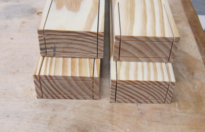
Dry fits...the tenons were all a touch fat
just as we wanted... |
 |
Stretchers with tenons and legs with mortises
all ready for dry fitting and final prep. |
 |
Dry run to test tenon-mortise fit... |
 |
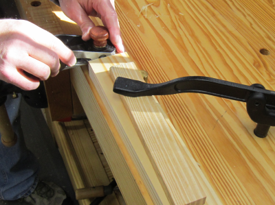
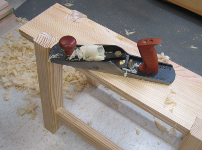
Touch up on tenon shoulders with Veritas
skew block plane. |
 |
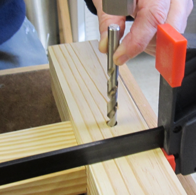
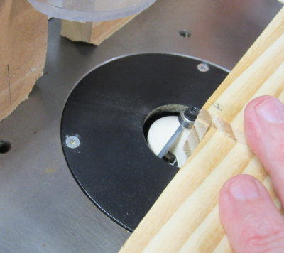
Drilling bore pin holes. |
 |
Setting bore pin location. We erred at this
stage and off-set the hole too far. We paid for this later... |
 |
Chamfered all edges that are exposed...on
the router table. |
 |
Chamfered the "to be exposed"
ends of the through tenons...used LN violin plane. |
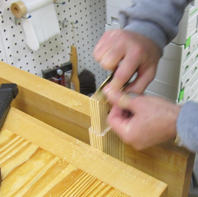 |
Draw bore pin install... |
 |
| Finished draw bore pin...most
of these broke due to too much off-set... |
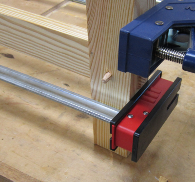 |
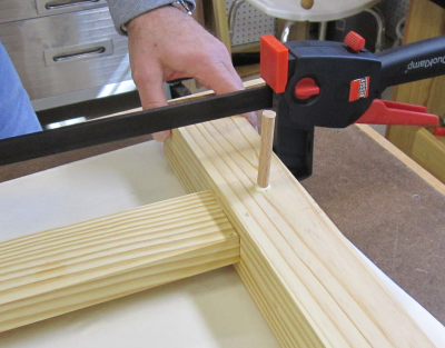
Leg and stretcher unit after glue-up...drawbore
pins cut with flush saws... |
 |
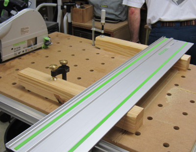
We compounded the pin error by failing to gang cut the bottoms of the legs before assembly. To fix...we set the TS 75 at 10° and cut the legs on the MFT3 table. |
 |
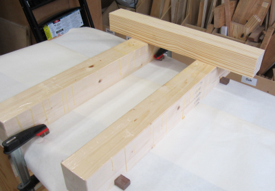
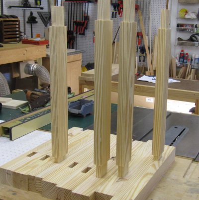
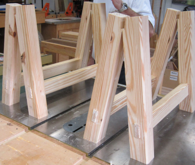
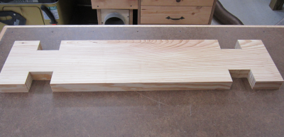
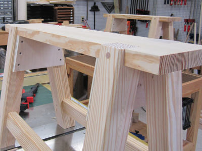
The finished leg and stretcher units. |
 |
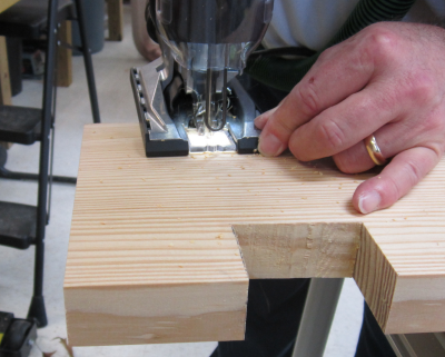
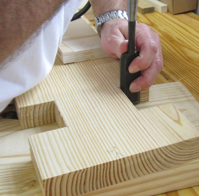
After laying out the notches for each leg
and stretcher unit, the notches were cut with Carvex jig saw. |
 |
Nishiki kinari paring chisels and LN floats
were used for final shaping to custom fit the notches... |
 |
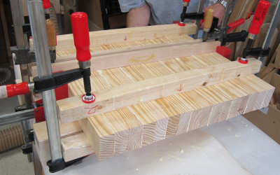
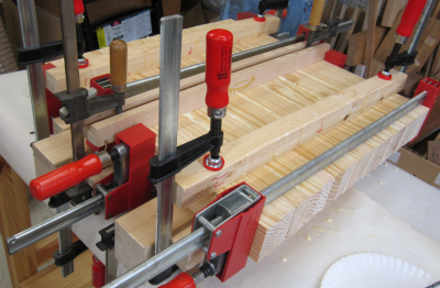
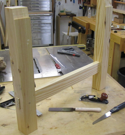
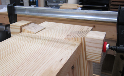
A top ready for assembly. |
 |
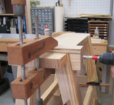
Some 10° cut-off blocks were used to
simplify the clamping... |
 |
After glue-up, protruding legs to be flushed... |
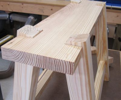 |
A japanese flush cut saw (no set) was used
to remove the protrusion... |
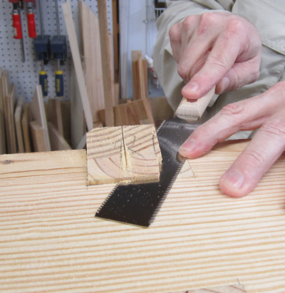 |
Veritas up-bevel #5 was used to smooth out
the cuts... |
 |
To make sure the leg pin dowel holes were
square and centered...made a jig with one of the angled cut-offs... |
 |
Jig in place, tape marked the depth of cut. |
 |
Oak dowel pins were pounded through LN dowel
plate. |
 |
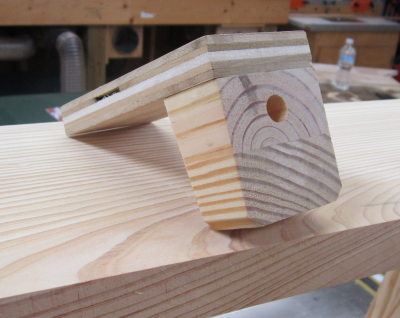
Dowel pins cut flush...plywood brace-support
pieces installed... |
 |
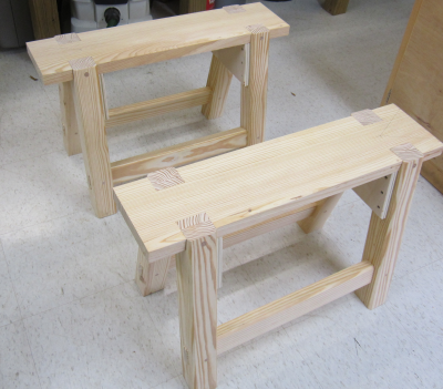
The matching pair...final stage of a finish
coat and some lower shelves and they will be ready for use... |
 |
|
|