Planning
Design
Milling
Final Assembly
Finishing
This is the second Moxon style bench top vise that I have built using the Bencrafted harware package.
I had been using the Moxon shown below as a third vise during dovetail drawer construction when James and I were both working on drawers. |
This Moxon style vise, from TFWW , was a pre-built model manufactured by the Philadelphia Furniture Workshop.
One of the features that sold me on this model was the cambered front jaw.
There was a catastrophic failure of one of the screws and I decided to build a second Bencrafted hardware Moxon. |
Here is the first Bencrafted Moxon that I made.
The build is shown here...
|
|
I knew the ins and outs of the Moxon design since I had been using Model1 for several years.
I wanted this one to serve different purposes and be quite flexible as to where I used it...so the first order of business was to think of how I wanted it to be different and how I wanted to to the same...
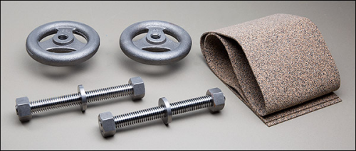
Number One on the same list...use the excellent Benchcrafted hardware package.
The package is identical to the earlier setup except that it includes Crubber, the Benchcrafted product, in lieu of leather.
|
|
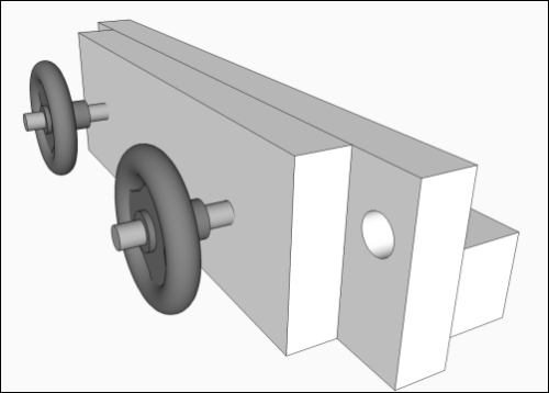
This is the Sketchup design of the Model2...it is based on a fixed rear jaw of soft maple, 24" long, 6" tall, 1.75" thick, the movable front jaw is soft maple and is the same height and is 19 inches long.
This means that the jaws are not as tall or as wide as the Moxon1.
The design aims to allow the vise to be secured well to the assembly table.
It will also be easy to secure at the workbench with clamps on the fixed jaw ends and holdfasts on the rear stabilizer.
|
|
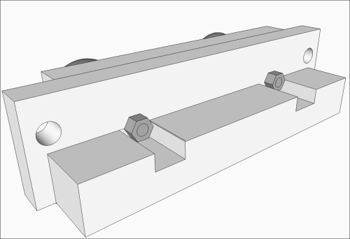
The rear stabilizer is hard northern maple and is 21 15/16 inches long, 3 3/8" wide and 2 15/16" high. The height will cause the stabilizer to be taller than the center of the jaws and thus will be higher that the bottoms of the rear nuts. I wanted the stabilizer to be taller, so as to be stouter and rather than altering the height the stabilizer will have dadoes that will allow access to the rear nuts.
|
|
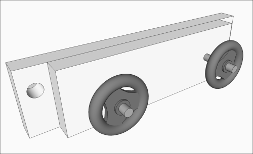
There will be ~12.25 inches between screws. This will easily accomodate nominal 1 x 12 stock. |
|
|
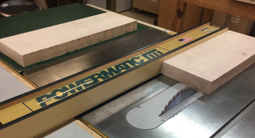
The jaws came from a 8/4 slab of maple. They were taken down size via bandsaw cuts, jointing two edges, planing surfaces and then ripping. |
|
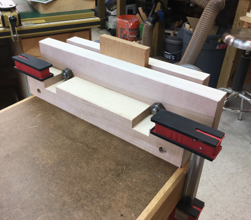
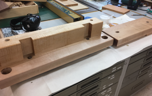
The chop blanks were from soft maple...the stabilizer is from 12/4 hard maple.
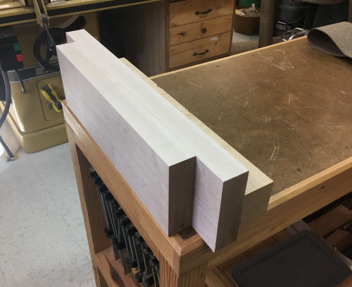
Here the blanks are set on the assembly table for a quick look before further milling.
At the assembly table the Moxon2 will be attached on the end of the table. The ends of the stabilizer are coplanar with sides of the assembly table for easy clamping. |
|
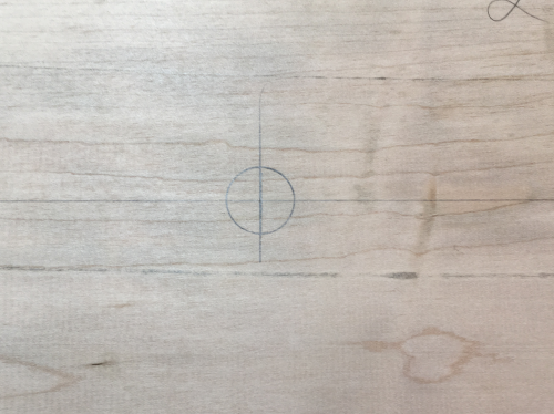
The rear chop needs two 3/4 inch holes...they are centered from top to bottom and they were centered 6 1/2 inches from the 12 inch center line of the chop. |
|
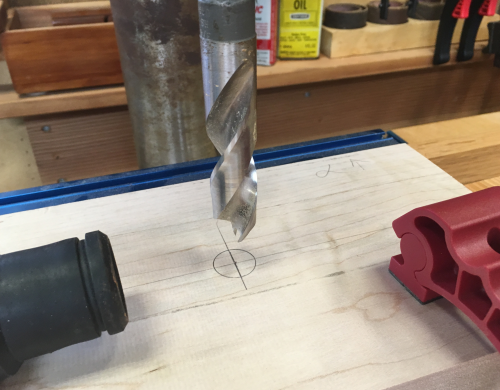
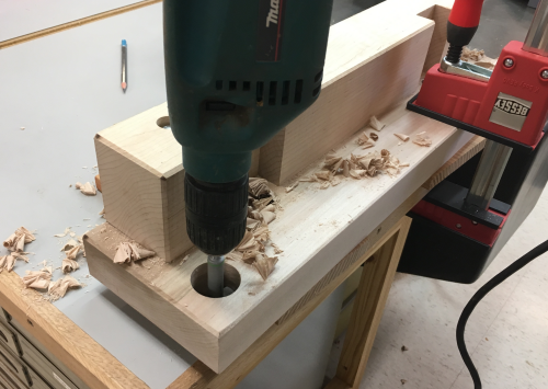
The holes were drilled at the press... |
|
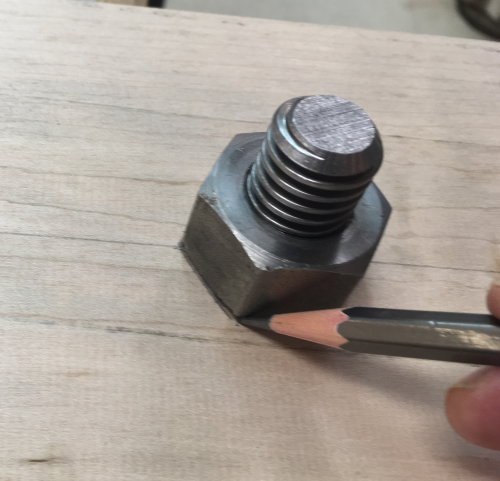
Then a screw shaft was laid into the hole on the front face of the rear chop and the bolt outline was marked out... |
|
This bolt area will need to be chiseled out to accept the nut and hold the bolt in place. |
|
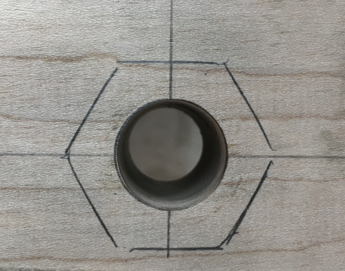
The hexagon area was chopped and pared with a variety of bench chisels...I found that the most effective method was to use a 3/4 LN chisel (the same width of one of the nut facets) to chop into each edge. |
|
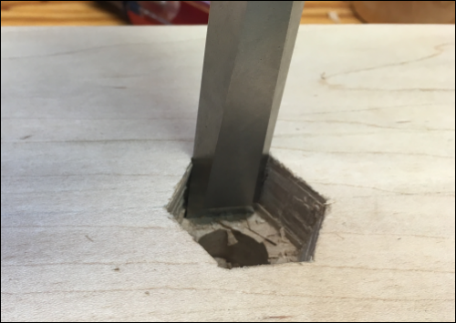
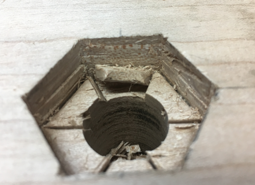
Then I chopped a line out from the corner of the faces toward the center hole...this broke the maple into smaller wedges. |
|
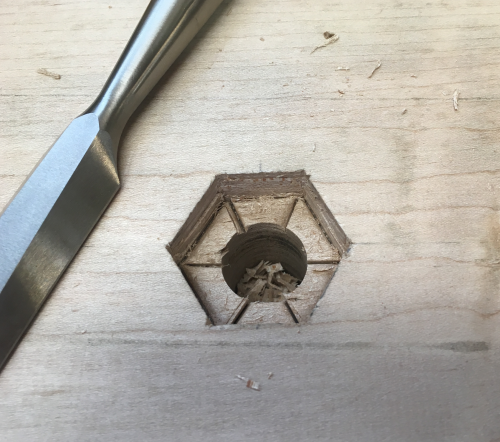
Then the wedges were removed with the LN small router plane. |
|
The "old woman's tooth" of the router plane made it easy to slice and then pry out the wedges. |
|
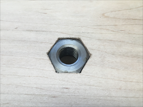
The router plane also helped to establish the final depth of 13/16" (the nut is 3/4" thick).
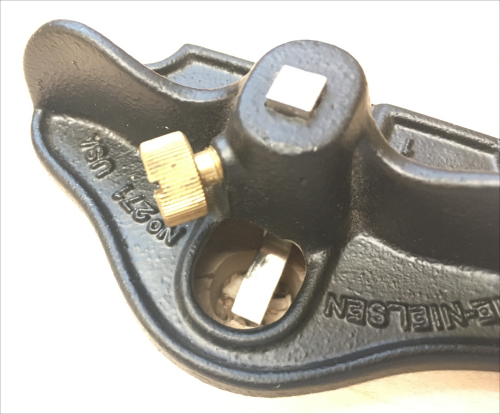
The nut in place, slightly below the surface.
|
|
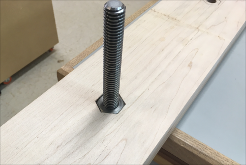
Holds tight for the screw to be threaded in... |
|
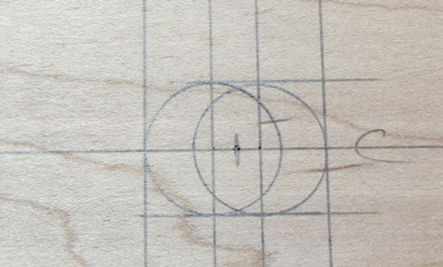
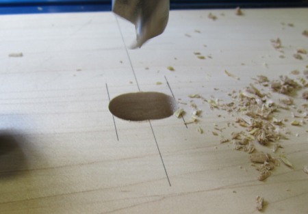
The holes in the front, movable chop had to be drilled differently...the hole needed to be an oval 3/4" tall and 15/16" wide rather than a circular 3/4".
This 3/16" of play will allow the outer, movable chop to be aligned askew...this will allow the vise to hold odd or tapered shapes. |
|
The layout had to be based on the outer edges since the center marks would disappear with the first drilling. Basically the two holes were drilled 3/32" off center and then gently the board was pushed to eliminate the central nubs.
The sides were cleaned up with Auriou rasps.
|
|
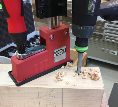
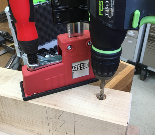
Drilled 3/4" holes with Zobo bit into the stabilizer leg to accept lag bolt heads and washers... |
|
...then 9/32" through hole for 5/16" lag bolt. |
|
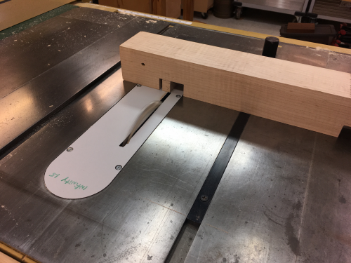
The stabilizer leg had two dadoes put in at the P66...used the Infintiy 1/4 inch thick blade to hog out these grooves... |
|
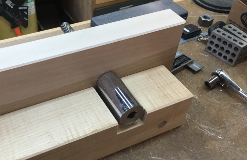
Test fit...the dado was designed to be wide enough and deep enough to put a large 1 1/4 socket onto the rear nut. |
|
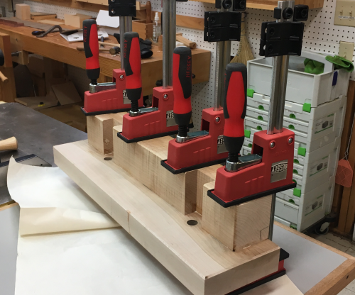
Then the stabilizer leg was lag bolted and glued to the rear chop. |
|
After drying...the chop and stabilizer were run across the jointer to make the bottoms coplanar. |
|
| |
|
|
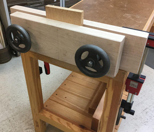
Rear nuts, the chop nuts, the screws were all put into place and locked down... |
|
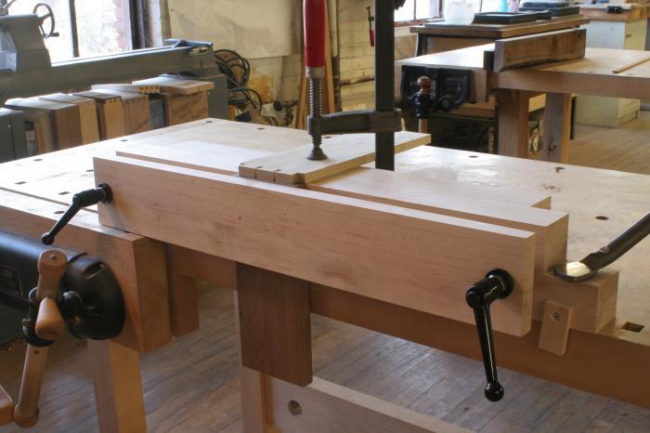
Here is the rear view of the vise attached to the end of the assembly table...being able to clamp the stabilizer leg of the unit down onto the table was the driving force for choosing the dimensions for this project. |
|
Front of the vise... |
|
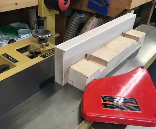
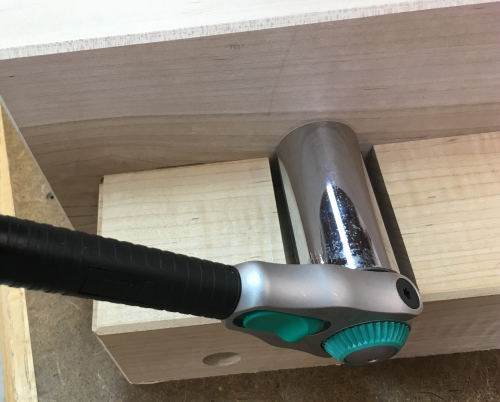
Holes for clamps were put into the extended ends of the fixed chop.
The 1 1/2 inch hole was drilled with a Zobo bit. I used the Makita drill for increased torque.
|
|
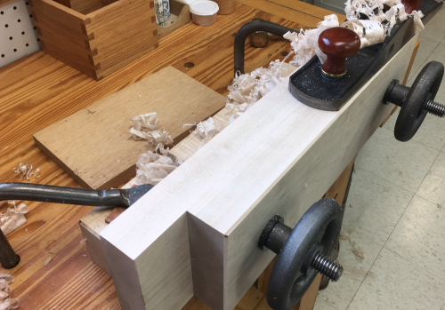
The tops of the chops were made coplanar with some planing with LV low angle jack. |
|
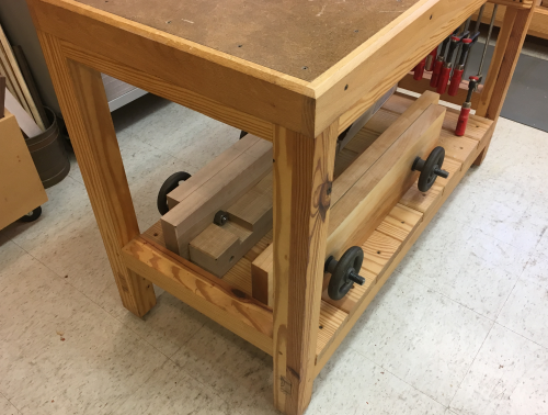
Storage under the assembly table for both Moxon vises . |
|
|
A couple of coats of boiled linseed oil was rubbed onto the surfaces that needed a finish...
|
|
To attach the Crubber, I used spray on Super 77 adhesive. |
|
I rolled out any bubbles... |
|
The crubber cover almost the entire inner face of the chop...left a 1/4 at the bottom.
I then cut out for ovoid holes for the screws and the unit was ready for use.
|
|
Finished product clamped to the main workbench...this is a rear view with Gramery bench dogs in place onto the stabilizer leg. |
|
The front view with clamps.
|
|