|
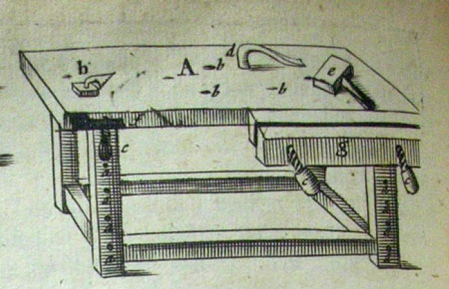
A Moxon style bench top vise seemed to offer great benefits. It may be used in a variety of places and in a variety of different ways. In its simplest form the Moxon style vise is a double screw that tightens two jaws. It is called the Moxon because it was first mentioned in the 17th century work...Joseph Moxon's "The Art of Joinery". In the image below (a portion of Moxon's Plate 4) it appears that the vise is floating in mid air in front of the bench. It is clearly a double screw vise but it has no discernible method of attachment.
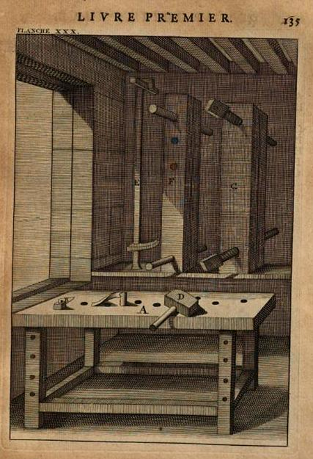
In a plate from Andre Felibien's "Principes de l'architecture" (1676) it appears that two vises are stored on a wall and thus were probably used on top of the bench rather than attached to the front of the bench. Moxon apparently copied much of Felibien's work.
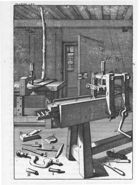
On a side note, another image from Felibien has a stick that is wedged between the workbench and the roof...this stick was used to apply pressure. It was called a goberge.
|
|
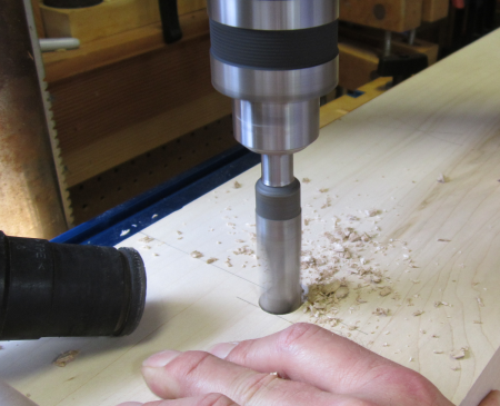
I purchased a modern Moxon style vise from TFWW , a pre-built model manufactured by the Philadelphia Furniture Workshop. One of the features that sold me on this model was the cambered front jaw. The other appeal was that it would be ready to go right out of the box and I really needed this setup for a project that we were working on that involved a number of half-blind dovetails (the machinest chest).
|
|
I liked it so much that I decided to build a second Moxon. It will be a bit sturdier and will use the magnificent Moxon hardware from Benchcrafted. Check out their video here. You may buy the vise pre-built...
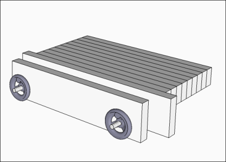
but I decided to buy just the hardware and design and build a model similar to the image below. This image shows an extended bench behind the vise jaws.
|
|
I searched the Internet and found the "bench on bench" model that I liked the most. This version of the Moxon had most of features that I was looking for...it was built by SC Rogers and can be seen here. It has dimensions similar to my needs, a bench with dogs, bevels to accomodate saw angle... |
 |
This is original Sketchup design of the vise... it is based on a rear jaw of maple,32" long, 7.5" tall, 1.75" thick, front jaw is the same but 28 inches long. The mini-bench part will probably be yellow pine. As I rethink my early design, I am considering moving the screws and handles more into the center...leaving more room outside of the screws.
|
 |
The hardware package includes the threaded rods, washers, nuts, wheels and a leather pad for the jaws. |
 |
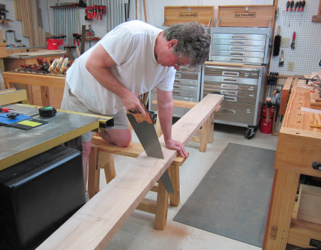
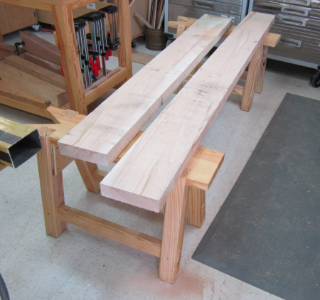
Wood for the vise jaws will be maple. I brought home a 8/4 slab x 12 foot by 7.5" wide board. I used a new Thomas Flinn Pax 22" crosscut panel saw to reduce the size. The long board was secured over the two saw benches and the far end rested on the Big Butt Stool. |
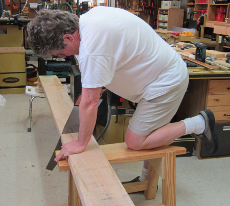 |
The reverse angle shows the saw benches. I like the saw. |
 |
The reduced slab. The piece on the left will become the jaws and the piece on the right will go into storage in the attic. |
 |
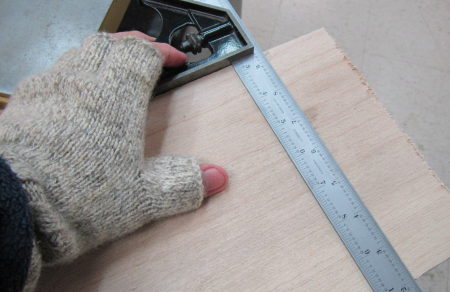
The next day I was laying out for the jaws...for a historical reference, note that I am wearing gloves. In the pictures above I am in shorts...true Mississippi March weather...yesterday was hot and muggy at 82°...last night the temperature fell to freezing, a total drop of 50 degrees ... |
 |
It was 32° when I woke up this morning and that was our high for the day...there is snow and ice and when I took this selfie in the shop it was 27° on the way to low of 21° tonight. |
 |
James came to town and after we finished the plane till (and the temperature rose to 70°) we got on the Moxon.
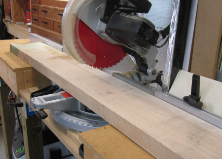
We cut the slab into the rough sizes for the chops. |
 |
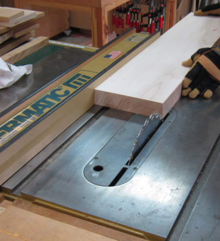
We cleaned a flat and squared one edge on the jointer. |
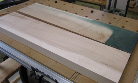 |
Then we planed to thickness. |
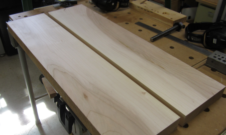 |
And ripped to width... |
 |
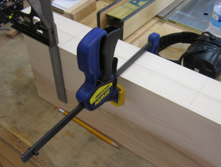
Layout referenced all measurements off the tops of the chops. |
 |
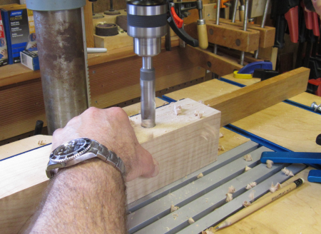
Drilled 3/4" holes into the rear brace to accept lag bolt heads and washers...then 5/16" through hole for the bolt. |
 |
The rear, fixed chop got two 3/4" holes to accept the Benchcrafted acme tapered screws. |
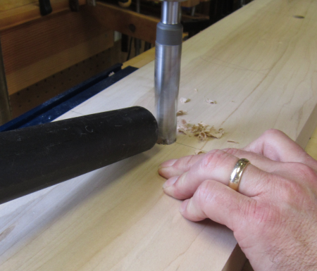 |
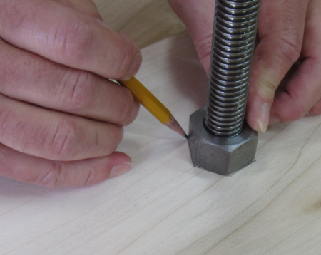
We then dropped one of the screws into the hole, threaded on a nut, and drew the outline of the nut on the inside face of the fixed chop.
|
 |
Then a chisel was used to clearly mark out the hole for the nut. We secured the chop on the bench and we were able to work on both cut outs at the same time. |
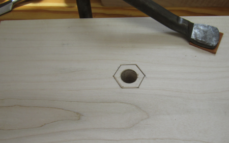 |
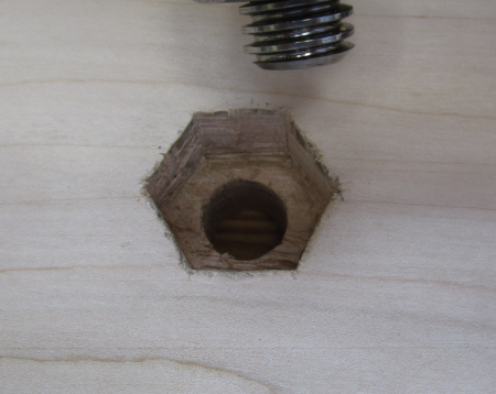
By the time we reached the depth appropriate to sink the nut below the surface the hexagon was not pretty...but effective. |
 |
The two holes... |
 |
Done... |
 |
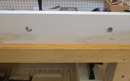
With the sunken nuts and the screws installed...this is the inner face of the fixed chop. There will be about 15.5+ inches between screws. |
 |
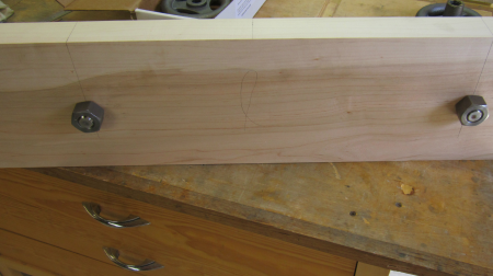
The rear face of the fixed chop with the locking nuts. |
 |
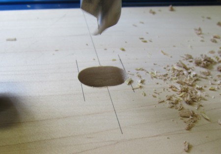
The holes in the mobile face had to be drilled differently...the hole needed to be an oval 3/4" tall and 15/16" wide rather than a circular 3/4". |
 |
The layout had to be based on the outer edges since the center marks would disappear with the first drilling. Basically the two holes were drilled 3/32" off center and then gently the board was pushed to eliminate the central nubs. This 3/16" of play will allow the outer, mobile chop to be aligned askew...this will allow the vise to hold odd or tapered shapes. |
 |
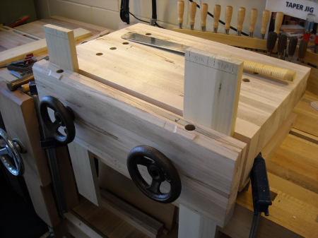
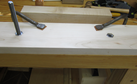
A dry fit...everything worked well. |
 |
The wheel turns effortlessly...a quick but powerful grab is available. In addition to the ~16" between screws, we can put a ~6" board on the outside of the right screw. We put 4" clearance on the left screw. |
 |
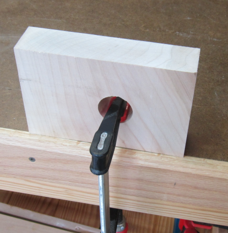
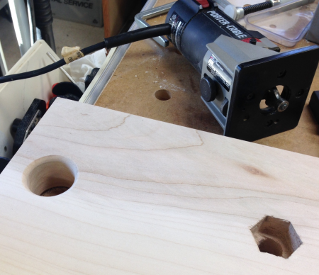
We did not know what size hole to drill in the fixed chop to allow for easy clamping...we did a test cut...used a 1 1/4" Forstner...liked the fit for the heavy duty Bessey Tradesman clamp. So we put two clamp holes into the fixed chop. The clamp holes are on the outer flange of the rear chop in the couple of inches that extends beyond the front chop. The large hole may be seen in the image below. |
 |
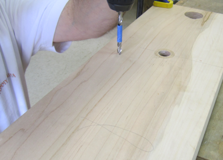
Final milling was a 1/4" pilot hole on the back of the fixed chop...this will accept the 5/16" lag bolt that will secure the back stabilizer brace to the fixed chop...it will also be glued. The pilot holes were drilled to a precise depth to avoid any splitting. |
 |
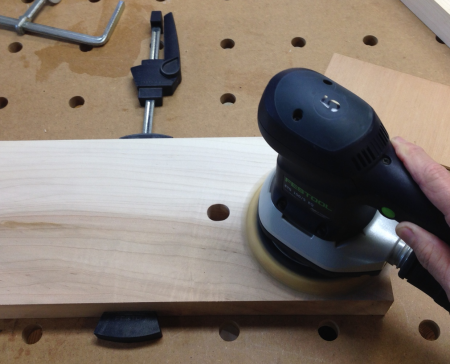
Final wood preparation involved sanding with the ETS 150 rotary sander through 80, 120 and 220 grits. |
 |
I routed a slight roundover on the inside edges of the clamp holes using a small trim router.
|
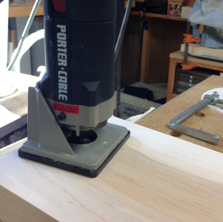 |
After the roundover and some sanding the edges are quite smooth and will ease tear out in the holes. I also chamfered all sharp edges of the chops with a block plane.
|
 |
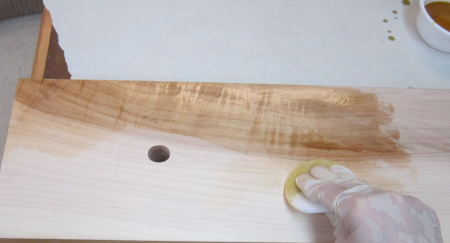
Chops were finished with three coats of boiled linseed oil. Dry time of 24 hours between coats. |
 |
Lubricated the acme screws... used Tri-Flow Superior Lubricant in the drip bottle. |
 |
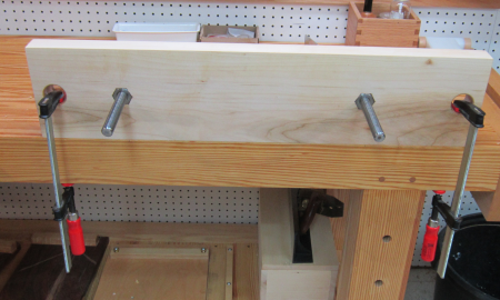
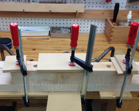
Mounting the rear brace...glued and secured with two 5/16" lag bolts. |
 |
Clamped... |
 |
Scraped off the glue... |
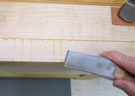 |
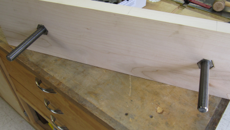
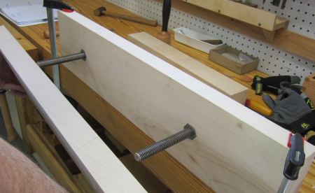
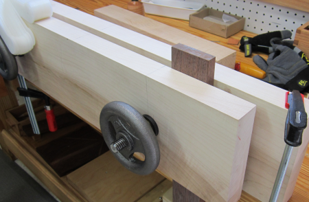
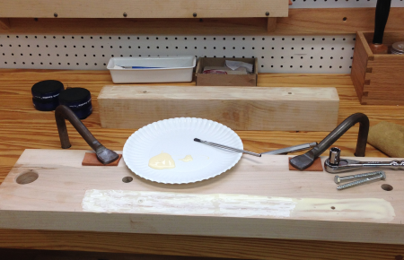
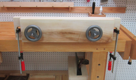
Test fit...clamps and hold downs...very solid |
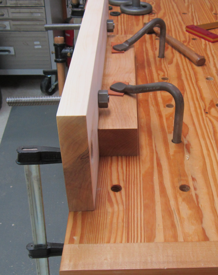 |
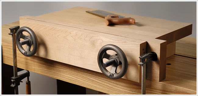
Front view with clamps on workbench. |
 |
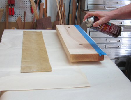
Applied the leather to the inside of the front chop...Super 77 spray adhesive... |
 |
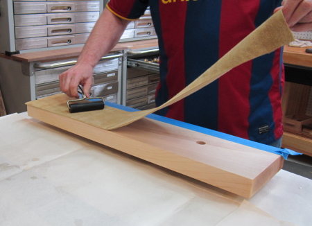
Rolled out any air pockets. |
 |
Trimmed leather to fit...used a Hock 1/2 striking blade in a knife holder. |
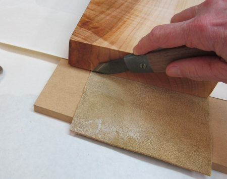 |
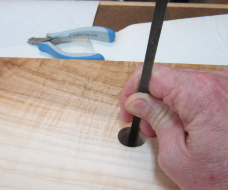
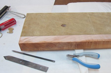
Cut out the holes for the acme screws from the backside...used a long Hock 1/4 inch striking blade. |
 |
Leather covers most of the inside face of the mobile chop from the top down to about the last 1 1/2 inches. |
 |
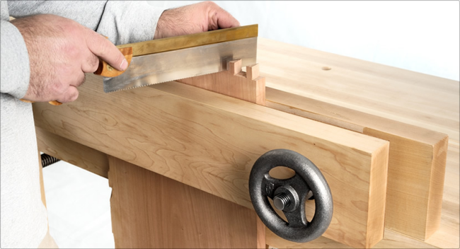
Moxon stored underneath bench... |
 |
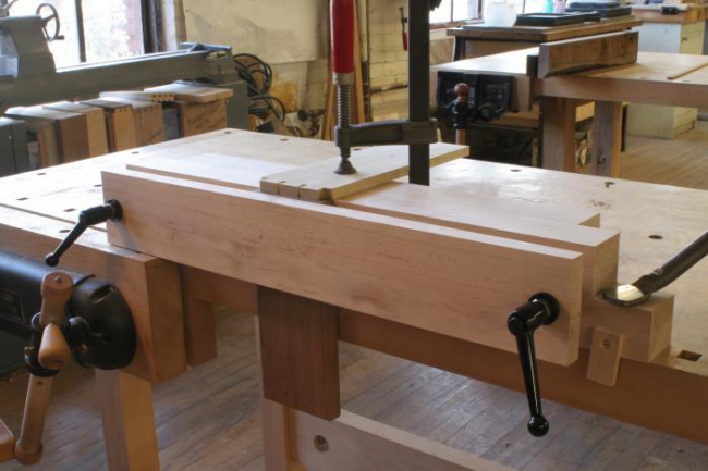
Unit in use... after assessing the unit I will decide whether to add the rear mini-bench and/or make some other modifications. |
 |
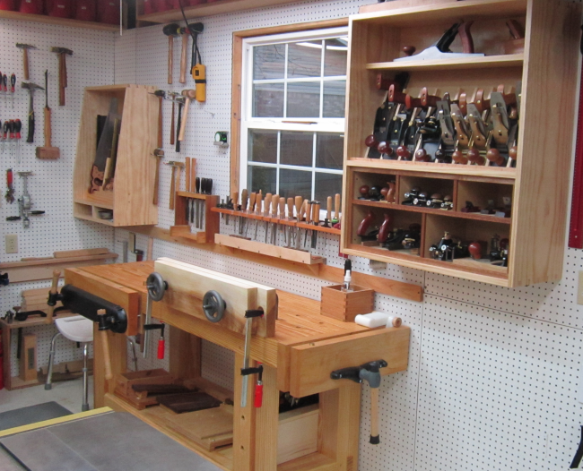
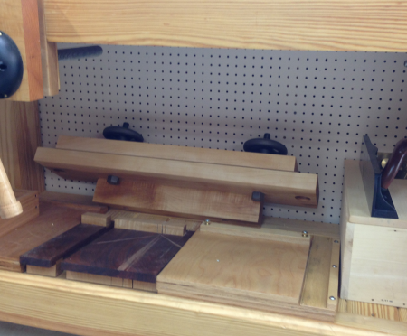
The three new shop items...saw till in the corner...Moxon vise on the bench... the plane till to the right...
|
|