| The original design of the curio cabinet was as a storage area for figurines for my eldest granddaughter. Her other grandfather has been giving her an age-related figurine on each of her birthdays. The company, Enesco, makes a series called "Growing up Girls" .
Phase 1: Plan Phase 2: Prototype Phase 3: Beta Build
|
|
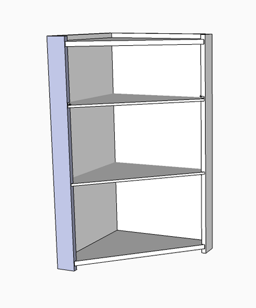
| I decided to make the unit a corner cabinet.
First Sketchup...
It was decided to make them in maple with two glass shelves. There were a couple of design requirements: 1. The distance from the back corner to the front face had to be less than 13 inches so that the cabinet would fit in the corner. This distance is from the wall corner to the edge moulding of a window frame. 2. The distance from the floor of the cabinet to the bottom of the first shelf had to be high enough to accomodate the tallest figurine in the Enesco series. 3. The spacing of the other shelves would decrease proportionally. |
|
|
|
|
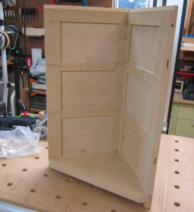
The first step was to make the prototype model. Having never designed or constructed a cabinet like this I had to figure out all of the details by making one...I used MDF for the proto. Materials would be predominately 1/4 inch and 3/4 MDF. The unit would primarily consist of two side panels with an angled front frame. |
 |
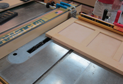
The side panels would have to have dadoes to accomodate the floor of the unit. This will be a sandwich of materials and will not be a standard router bit size. So they would need to be cut using the Freud dado set on the tablesaw. We created a sacrificial fence and a zero clearance for the dado setup.This will minimize tearout. |
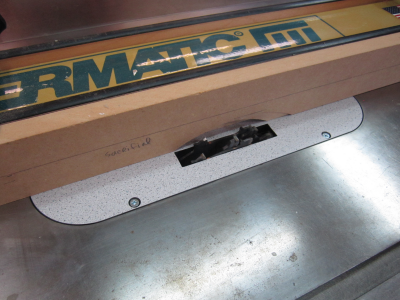 |
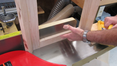
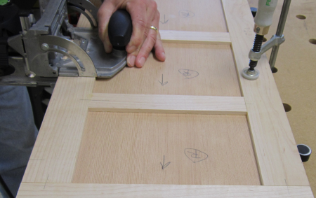
This set up enabled us to crosscut the panel using the Incra mitre gauge. |
 |
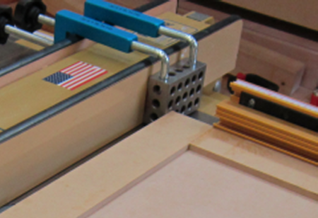
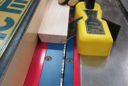
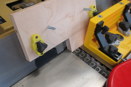
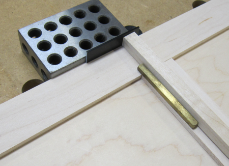
To increase ease of measurement and to promote safe cutting, I used a couple of Rockler fence clamps to hold a 1-2-3 block in place. This allowed the fence to be precisely set by adding 1 inch. The placement of the block allowed proper setup but as the panel goes forward there is not binding against the fence. |
 |
The dado. |
 |
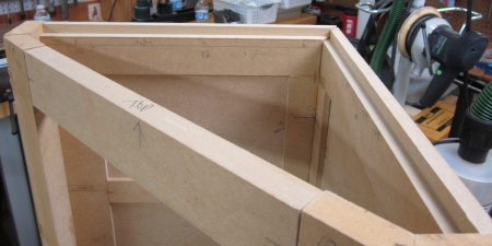
In the proto the panels were to be joined in the rear corner at 45° . After the mitres were cut on the tablesaw, Domino tenon slots were put in place. |
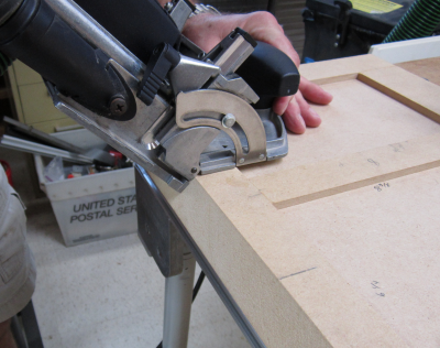 |
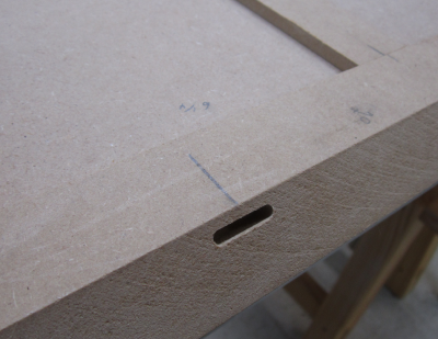
Mortise slot for the Domino tenon. |
 |
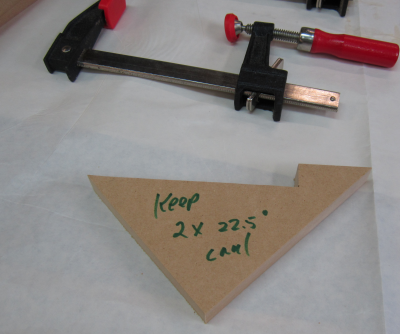
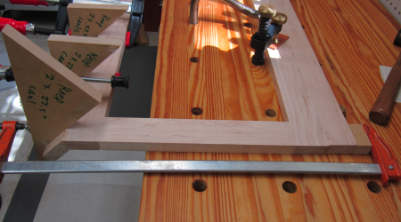
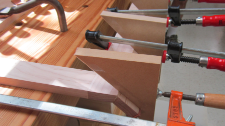
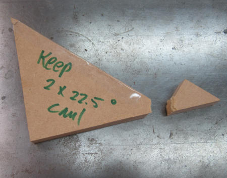
The front stiles join at 45° . The angles are thus 22.5° . It was difficult to put clamps onto the angled surfaces. We made some cauls that would create a better clamping surface. |
 |
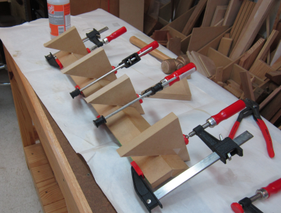
The cauls and clamps in use for glue up. |
 |
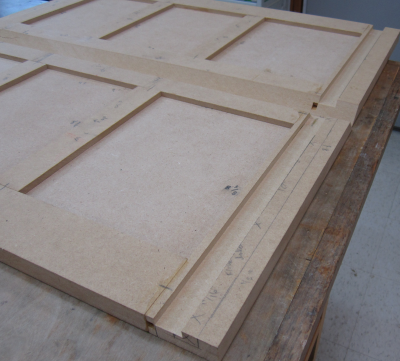
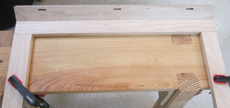
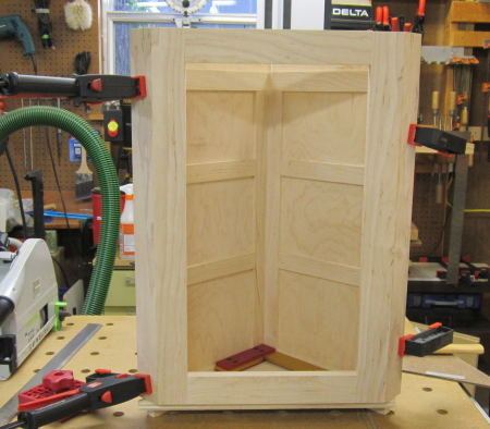
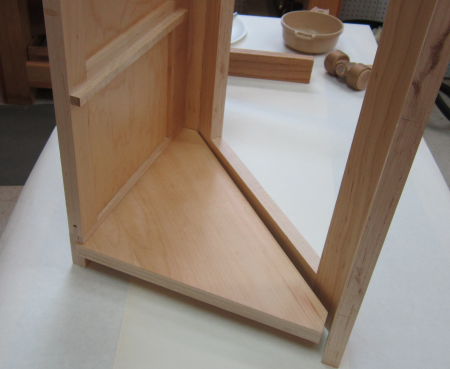
The prototype was never totally glued together...the main purpose was served once the pieces were dry fit...here the shelf placement is tested. Cleats will be used to hold the shelves. During the proto build, I created a template to define the shape of the shelves. The original plan was to have glass shelves. But my local glass cutter suddenly went out of business and I decided to make the shelves of wood so that I would not have to develop a new sources. This reduced project dependence on outside sources of materials. |
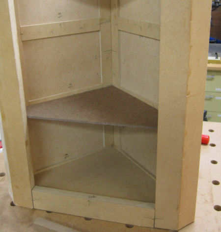 |
For the top, a rabbit was routed into the side panels...a cleat will be used to support the front. This will allow the plywood top to be dropped in after the shelves are in place. |
 |
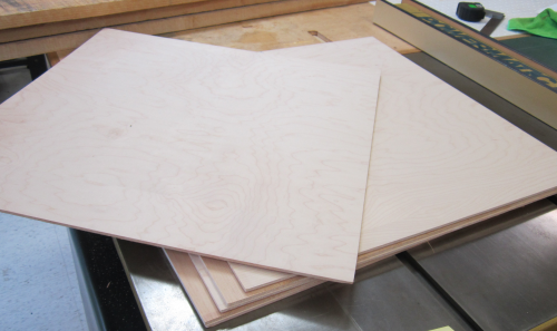
After the construction details were determined, it was time to build the Beta unit. It will be made from maple. Panels will made using 1/4 inch maple plywood. No local suppliers exist for this product so the 24 inch x 24 inch sheets were purchased from the Internet. As is typically found today, the actual thickness is less than 1/4 and this fact will cause problems when it comes to creating the dadoes for the panels.
|
 |
Additionally I have some remanants of 12/4 hard maple slabs that my brother Tom had brought me from Virginia. These were left after the bench vise construction. This wood will be used as needed. |
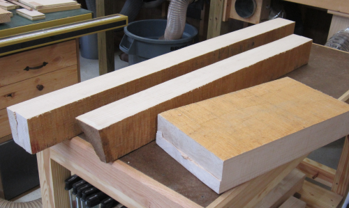 |
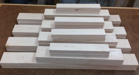
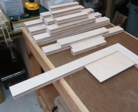
5/4 hard maple was purchased locally. |
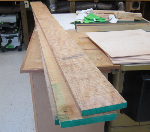 |
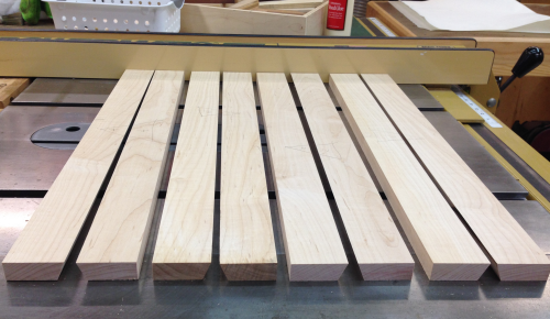
...and jointed and planed to 3/4 inch stock. |
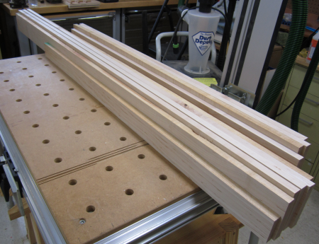 |
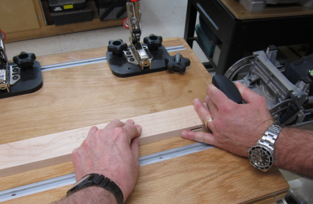
Side and front stiles would be 2 inches with a 22.5° bevel. |
 |
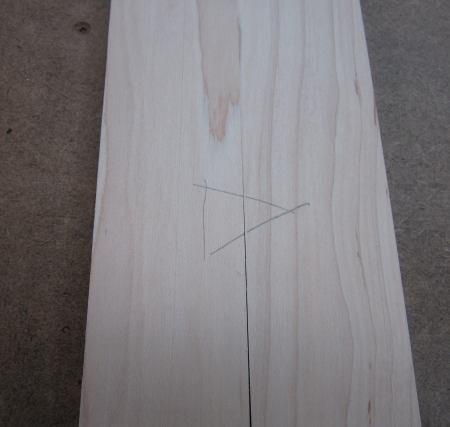
The board was flipped make the bevel on the other side that the grain at the joint would wrap around. |
 |
After angle was properly achieved the board was ripped to width.
|
 |
The side and front stiles stiles...bevelled at 22.5° |
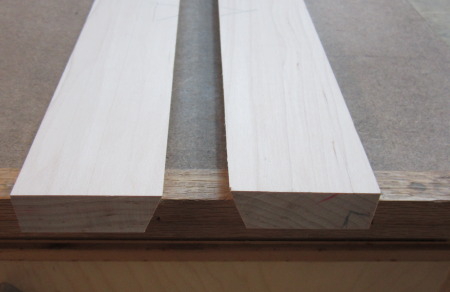 |
The front and side stiles were marked to make sure that all milling would result in the wrapped grain look at the joint. |
 |
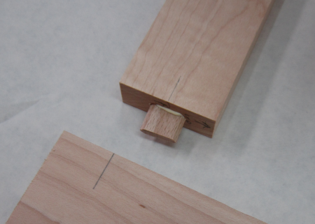
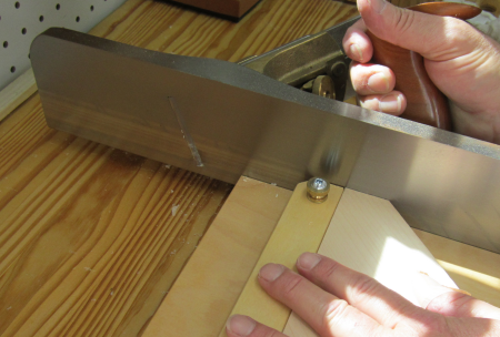
Ends of the rails were guaranteed square by shooting with LN 51. |
 |
Rail with mortise and floating Domino tenon. |
 |
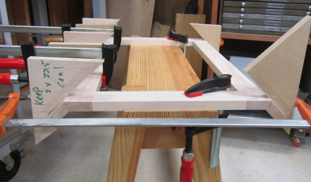
Front face glue up...the matching stile angles were used on the outside edges to get a better clamp angle. Two cauls were used to keep all pieces coplanar. |
 |
Front panel after gluing...you can see the side 22.5° bevels where the front stiles will join with the side stiles. |
 |
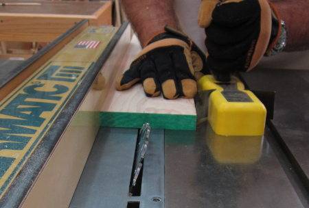
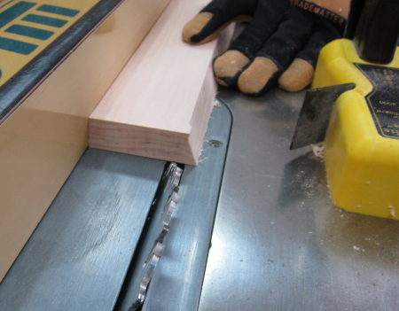
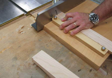
After the side stiles were bevel-cut on the table saw they then sat a couple of weeks. They bowed...we decided we needed to clean up the bevel so that joint would look good on the front face. After examining several options we decided to clean up the bevelled surfaces on the jointer. The fence was set to 22.5° and a magnetic jig was used to hold the piece tight against the fence. |
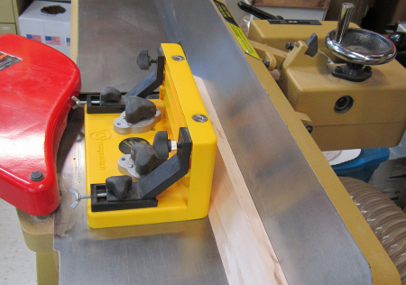 |
A shop-build mag jig was secured to the fence to hold down the work piece. The cutter heads were exposed, but we made sure that all flesh was never in proximity to the cutter heads. |
 |
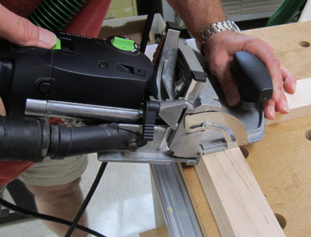
| The jointing went well and the stiles were ready for the cutting of 5 Domino slots...here the side stile face piece is placed in the jig. | 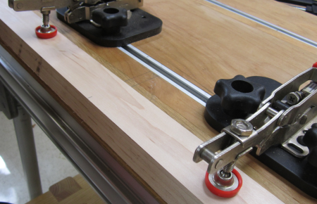 |
The mortises were cut to accomodate the smallestDomino tenons...#4 x 20 mm. Here the mortises are being cut into the frame. |
 |
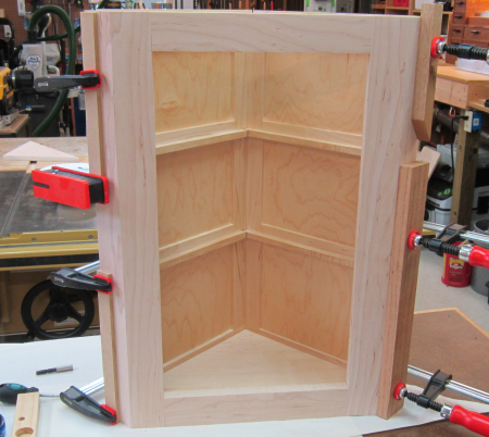
The glue-up of the side stiles to the face frames... |
 |
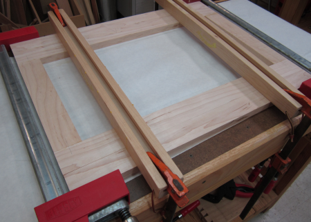
The clamping process was made difficult due to the angles...the frame was secured to the bench... |
 |
The shop-made cauls helped dramatically. |
 |
To glue up the second rail we would need a couple more cauls for the long clamps and we had a blow-out of one of the MDF cauls...so we made three new ones in Birch ply. |
 |
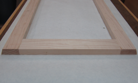
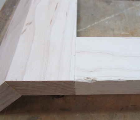
Due to the odd angles of the face frame the unit could no longer be clamped to the bench...we moved it to a saw bench and secured it. The first joint looks really good. |
 |
This image shows how well the cauls worked...they allowed the clamping to pull the joint nice and tight...good glue squeeze out... |
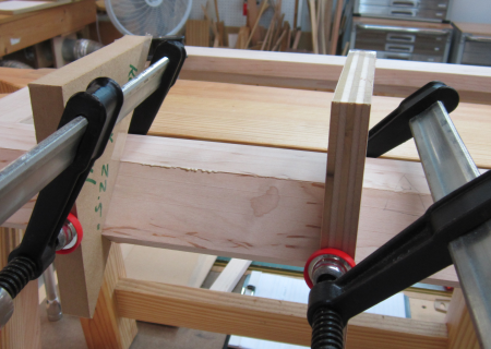 |
Image shows the three short run clamps and the two long clamps at the ends...these long clamp positions are the ones that required a caul on each end. |
 |
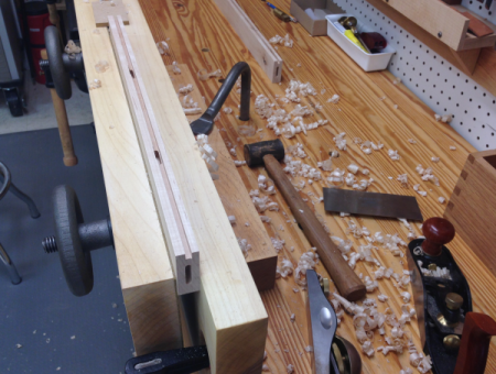
After glue-up, the face was clamped to the bench for suface clean up with a cabinet scraper. |
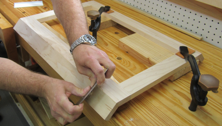 |
This went beautifully until a push across the joint went onto cross grain and spelched out the front edge of the top rail. |
 |
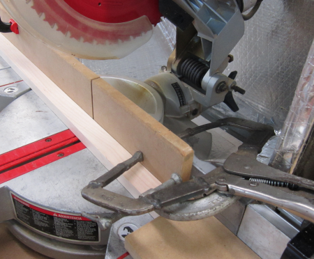
To fix the spelch we went to the jointer and created a thick push stick to run the top rail across the cutter blades. This backer-board was to prevent further spelching. |
 |
This setup worked very well and the front face frame was jointed 4 times to remove the spelch blow-out. The side panels were jointed to match the height of the front face frame. This spelch repair fix worked very well. |
 |
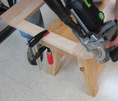
Next step on the face frame was to put in the mortises that will join the frame to the panels. The angle makes it difficult to clamp the frame to the MFT3 table so we used a sawbench. |
 |
This provided the angle to put in the mortise with the proper reference point. |
 |
Making the panels...cut the cross rails to length...had a blow out on the backside...threw up a sacrificial fence to stop that |
 |
Domino mortises were cut into all of the rails and stiles for the panels. Here we are putting a mortise in the end of one of the long side stiles. |
 |
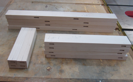
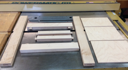
Panel rails and stiles with all Domino mortises done. |
 |
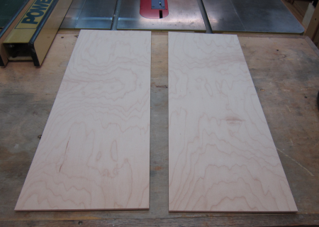
The maple plywood was ripped to the proper width for the panels. |
 |
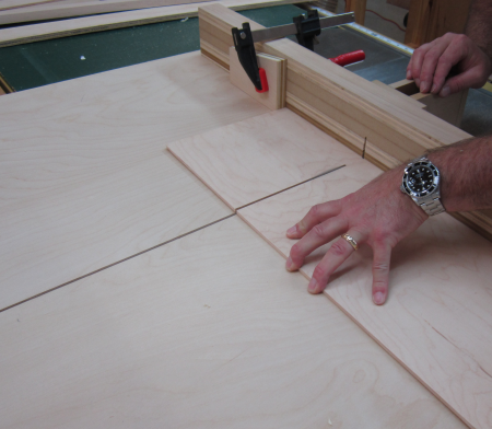
Then the panels were crosscut using a sled for safety and repeatability. |
 |
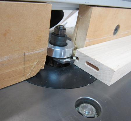
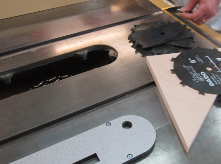
Dadoes for the plywood had to be cut into the rails and stiles. Because the thickness was not a true 1/4 we could not use a standard router bit without having a sloppy fit. We used a Freud slot cutting stack. |
|
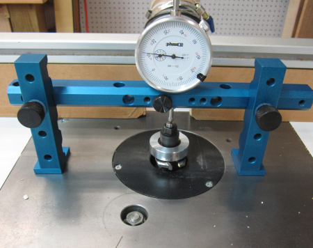
However, due to the stacking cutter blade thickness differentials we could not make the stack come out perfectly. The fix was to cut the slot slightly tight then run another pass to widen it appropriately. The first step was to precisely measure the height of the spindle.
|
 |
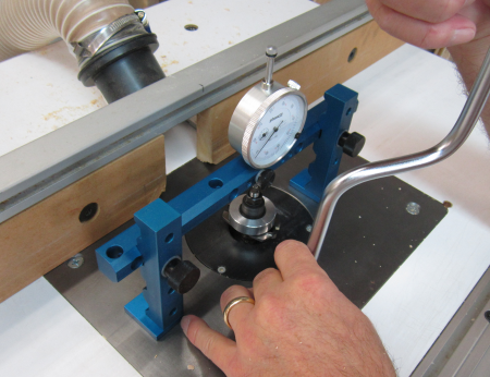
Then the slot cutter was raised .012 of an inch to give the perfect fitting slot. (After gluing up the first panel we decided that the "perfect fit" was too tight. Next panel we will adjust the slot another .004 of an inch.) |
 |
Here is how the panel fit into the grove. |
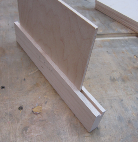 |
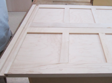
Dry fitting to make sure that all the grooves look correct. |
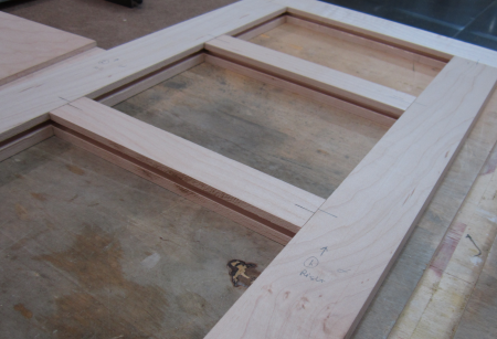 |
Panels put together...dry fit. |
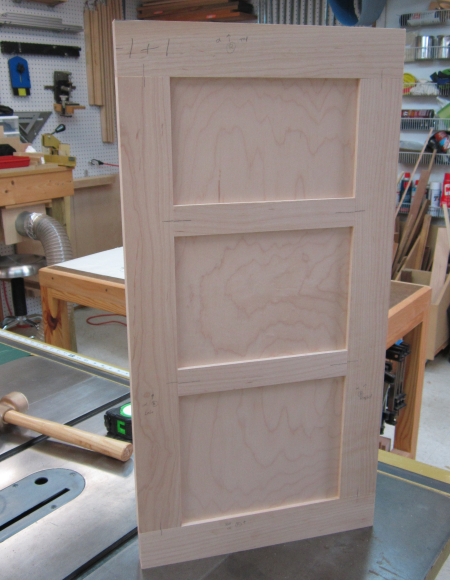 |
Glued up panel #1. Had some issues with plwood being overly tight. The mortises on the lower rail were also too tight. We will make next panel with adusted milling.
|
 |
The second panel build...the slot for the plywood was enlarged approximately .012 inch. Materials ready for glue up. |
 |
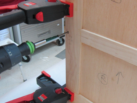
One rail and stile joined with a Domino mortise/tenon joint. |
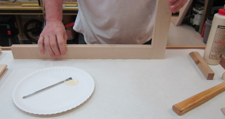 |
Top panel inserted to float in groove. Mid-rail joined with glued M/T joint. |
 |
Middle plywood panel inserted...free float. |
 |
Second mid-rail joined...glued with M/T joint. |
 |
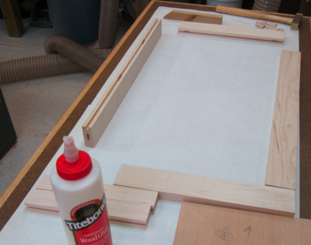
Ready for stile...M/T joints will all be glued. |
 |
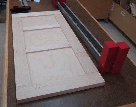
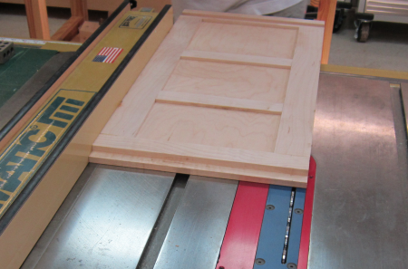
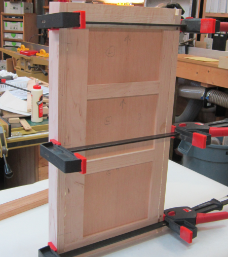
Second panel...squared and clamped. This panel went together with less grief due to wider grooves. |
 |
The panels needed a groove in the bottom rails to accomodate the 3/4 inch plywood floor. Of course, the ply is not a true 3/4 so a dado stack was set up on the tablesaw to cut the appropriate groove. |
 |
Here are the two panels with grooves in bottom rails. |
 |
In the prototype build the back joint for the two panels was done with a mitered 45°...for the beta unit we decided to go to a butt joint so we ripped 3/4 inch off the right panel. |
 |
Then mortises were milled into the sides of the panels that will join with the face frame. |
 |
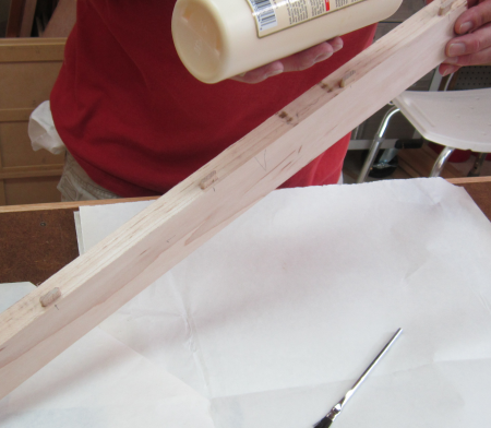
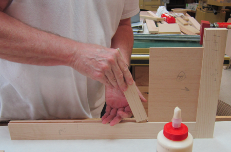
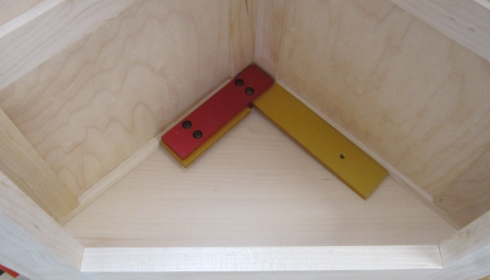
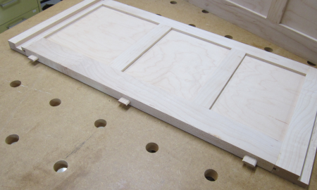
After a dry fit it was time to put in the shelve supports, this was done using real Imperial spacers rather than measuring...cuts down errors dramatically. The bottom edge reveal was 3/16...the end spacer was 1/16. The shelves were glued and pinned with 1 inch # 23 pins. Final prep before finishing was a full sanding run thru grits up to 240. |
 |
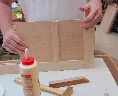
After the panels and the front face were built it was time for a dry-fit to confirm the size of the floor and the shelves. |
 |
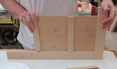
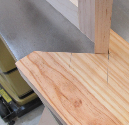
The floor plate was cut using a template from the proto-type build. A 5/16 guide bushing was used to increase the plate size so that it would protrude into the grooves. For the beta we went with maple 3/4" plywood. The test piece was then placed into the grooves, the panels were squared and the corners were marked. |
 |
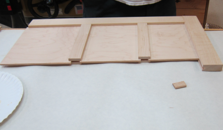
After trimming off the corners of the floor plate, the piece was dry-fitted again...here it is clear that the cut leaving the line means that the floor does not meet the front face rail. |
 |
Micro adjusting the corner edge by shooting the end with the LN51... |
 |
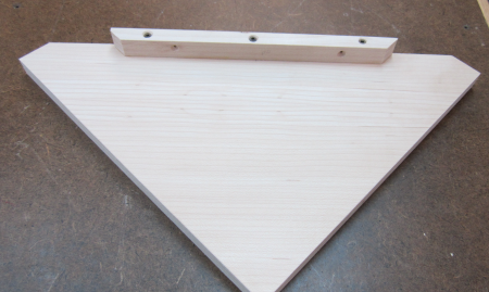
After the floor plate was correctly sized, a glue/clamping block was added to the bottom ege of the floor. This will provdide a clamping surface to draw the floor plate to mate with the inside edge of the lower rail of the face frame. Two screw holes are pre-drilled to make the glue & screw easier to pull off... |
 |
After the mortises were milled into the frame and the panels, Domino tenons were installed. |
 |
Then came a dry fit... |
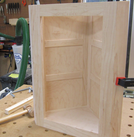 |
Everything came together well. |
 |
After the interior pieces received some finish, the carcase is ready for assembly. |
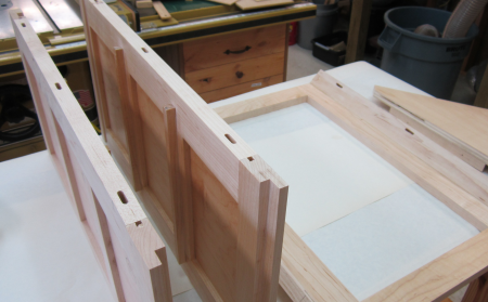 |
Here are the panels prepped for glued up. The Domino mortises are tight on the panel edges and loose on the backside of the front frame. #5 x 30 Domino tenons were put into the tight mortises. |
 |
First panel to go in is the left, narrow one. |
 |
Then the floor plate was slipped into the grooves. There will be no glue here. |
 |
The wider, right plate was then installed and clamped to form the ninety at the back. |
 |
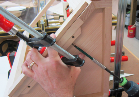
Then #8 1 1/2 inch screws were countersunk...five of them to make the back angle glued and screwed. |
 |
The floor plate was then secured to the backside of the front face frame from the bottom.
The floor plate floats freely in the slots of the two side panels and the floor plate cleat is attached with two small #6 screws and no glue to the face frame. |
 |
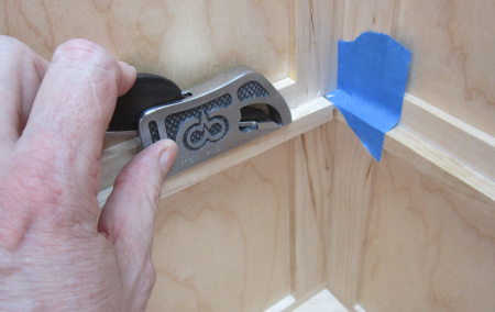
Once assembled there was a small differential in shelf support heights...some work with a paring chisel and a Clifton mini bullnose shoulder plane took care of that. |
 |
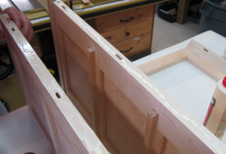
The first application of shellac will be to all of the inside surfaces. This is done prior to carcase glue-up to simplify the application. The surfaces include the inside of the face frame, the inside of the two panels and the top of the floor plate. Tape was applied to prevent shellac from being rubbed into a surface that needs to be glued later.
|
 |
The first coat of 1 lb. cut Super Blonde shellac was padded on. 0000 steel wool was used to defuzz and then a second #1 lb cut was padded on. |
 |
Then a #2lb cut was padded on. Grain is starting to pop. |
 |
After these finish coats the carcase was assembled...the interior has been finished with padded on shellac and the outside frame has not. The interior coat will get a final brushed on #2 lb cut Super Blond shellac. |
 |
The shelves and the top received shellac before final assembly. |
 |
Top assembled... |
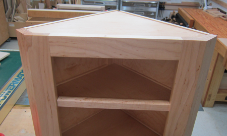 |
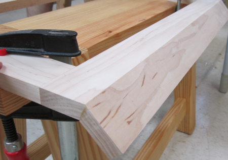
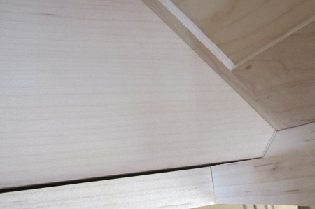
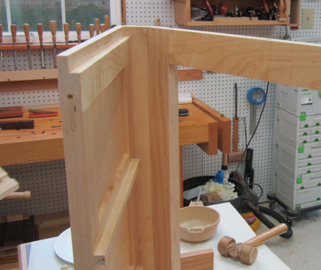
Rear corner |
 |
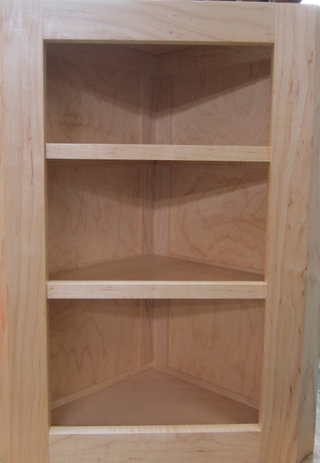
Dry run with the shelves and top in place...some shellac touch ups still remain in the corners... |
 |
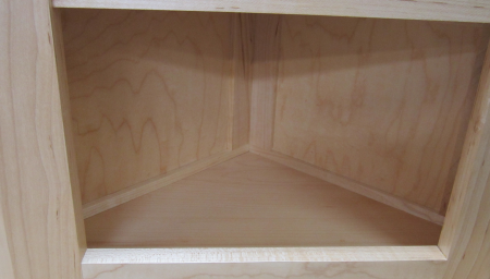
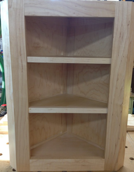
Interior view of bottom shelf... |
 |
Front edges installed on shelves. Finishing coats of shellac is all that is left. |
 |
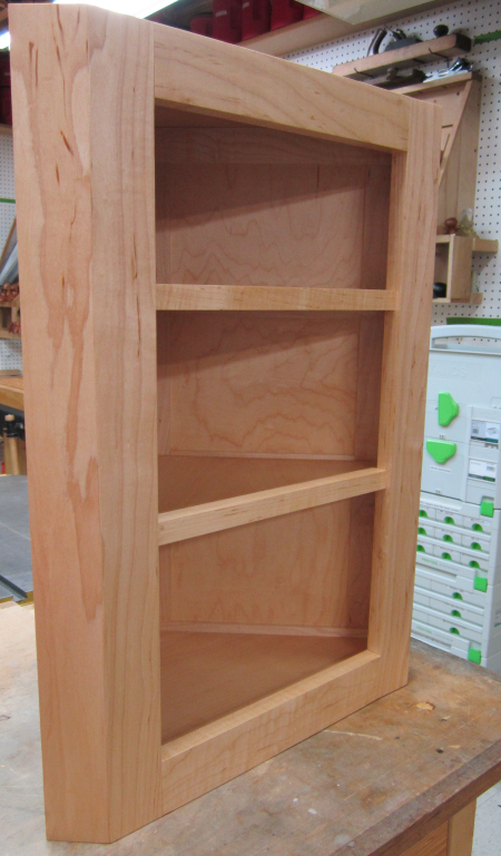
Final frontal view of beta unit... |
 |
Side view of beta unit... this cabinet will go to Sarah... |
 |
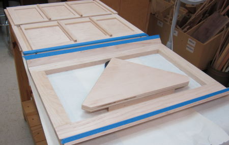
After completion of the beta unit...I had to build two more...for Hannah and Lydia. The maple had been milled to thickness and to rough widths and lenths during the beta build. Here the rails and stiles for the four panels have all been selected and finished to slightly oversized. Each panel has two stiles, two main rails and two divider rails.
|
 |
Then all of the panel grooves were routed. The undersized "1/4 inch" plywood is actually .20 inches...the slot cutting blade used was 3/16 inch (.1875)...so Cindy and I made a pass on all the rails and stiles and then lowered the bit .015 inches for a final .20+ that created a tight fit but with enough room for play. |
 |
Here a panel stile is shown with Domino mortises and the the groove for the panels. |
 |
Here are all the pieces ready to assemble a side panel. A miscalcuation on the panel cuts made the overall height of the unit 2 and 3 to be shortened by 1/2 inch...but overall the better groove fits and some adjustments on the Domino fits made assembly much easier. |
 |
As before, all of the front stiles were cut on 22.5 degree bevels and the grain patterns were wrapped around the stiles. |
 |
There had been some problems using router cutters to cut the dadoes for the floor...so I secured "undersized plywood" router bit sets. So we cut the grooves using the Festool router and a 23/32 bit. |
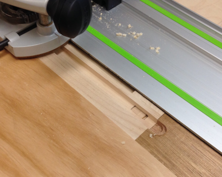 |
After the panels were grooved there was minor disaster when a grain line blew out in the panel groove during a dry fit. |
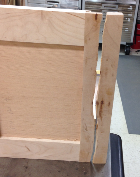 |
During the glue up for the panels we brad nailed, glued and clamped the fault line. |
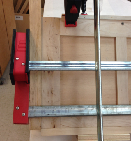 |
With great results... |
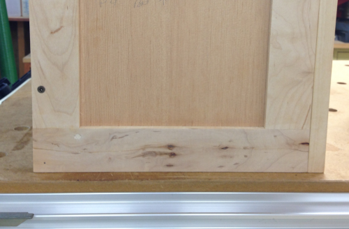 |
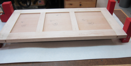
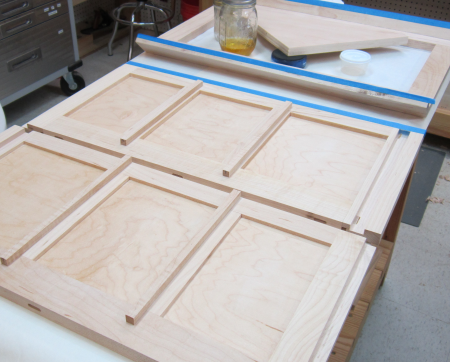
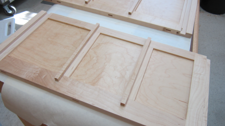
After glue ups the shelf supports were put in place... |
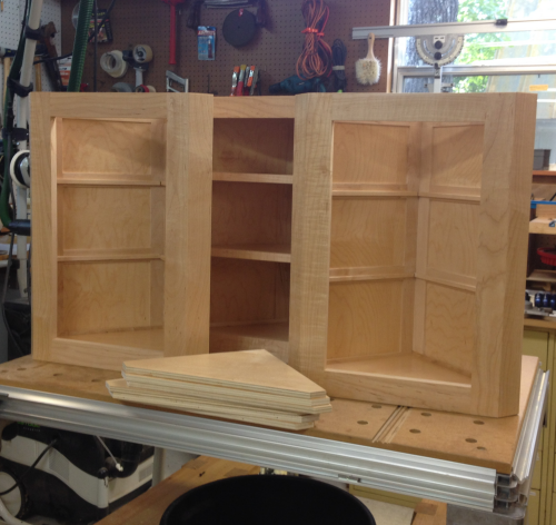 |
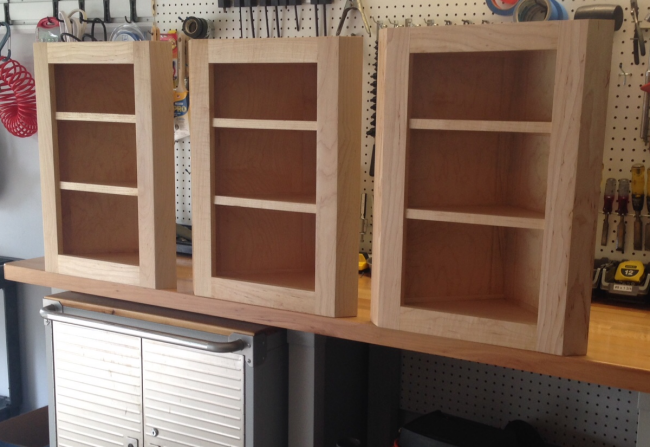
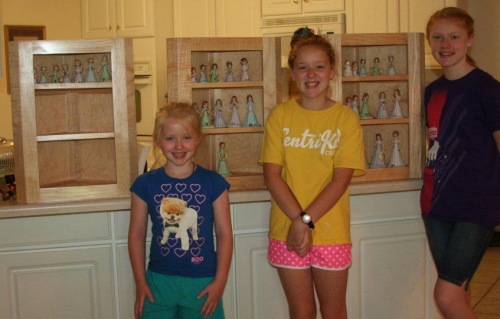
The three finished cabinets ready to be transported to the Grands...
|
|
|
|
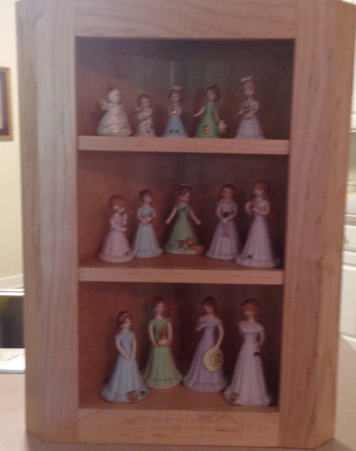
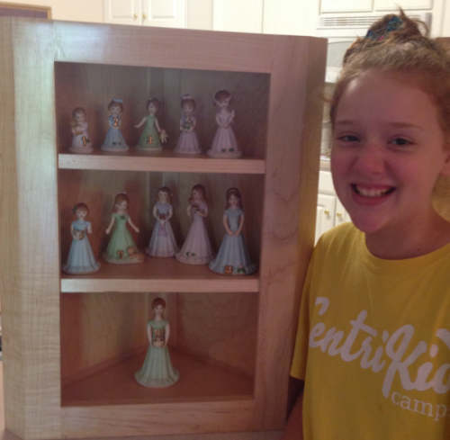
| Sarah's figurines |
 |
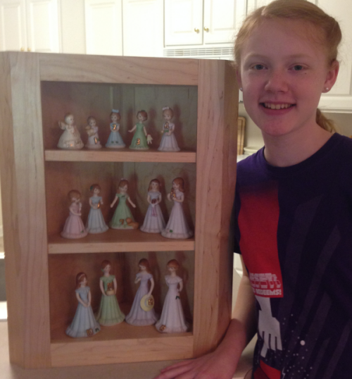
Sarah and curio |
 |
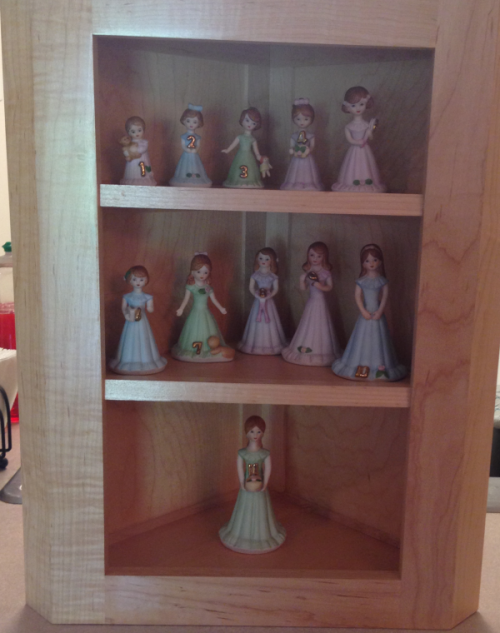
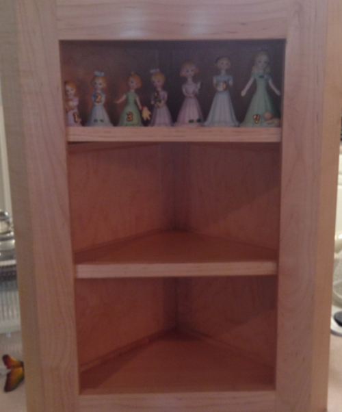
Hannah's figurines |
 |
Hannah and curio |
 |
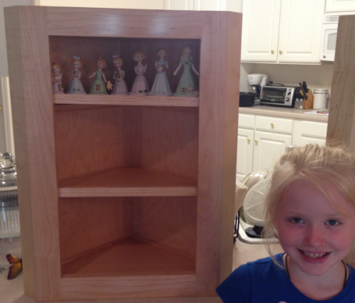
Lydia's figurines |
 |
Lydia and curio |
 |
the three grands... |
 |
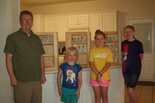
Grandad with the grands... |
 |
to be installed...
|
|