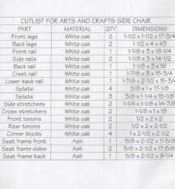
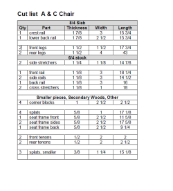
|
Joinery Milling: Front and Back Rails Joinery Milling: Splat Assemby, Crest and Lower Rails Joinery Milling: Mortises and Tenons for Side Stretchers Joinery Milling: Dovetails for Cross Stretchers Finish Selection and Application
|
|
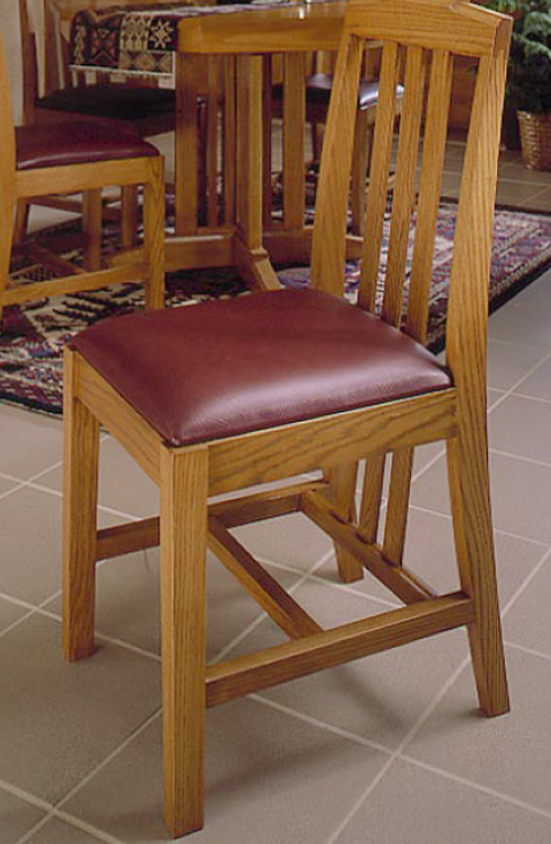
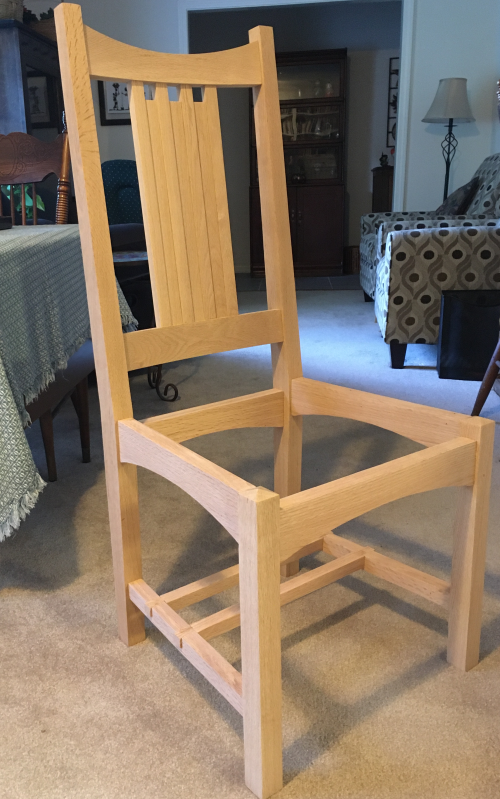
This will be the first chair that I have built. Cindy and I looked at a number of chairs online...liked some of the Mission stylings of this Stickley chair.
|
 |
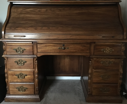
The chair's primary purpose will be its use at an oak rolltop desk...width limitation is 21 1/4 inches. Secondarily, it will serve as a reserve dining chair when guests outnumber chairs at the table. |
 |
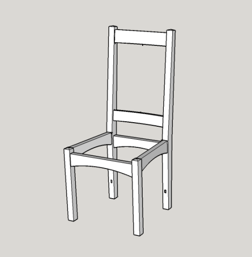
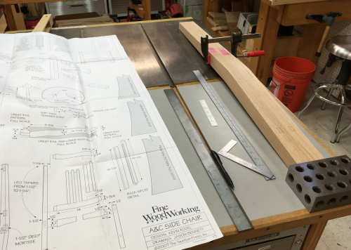
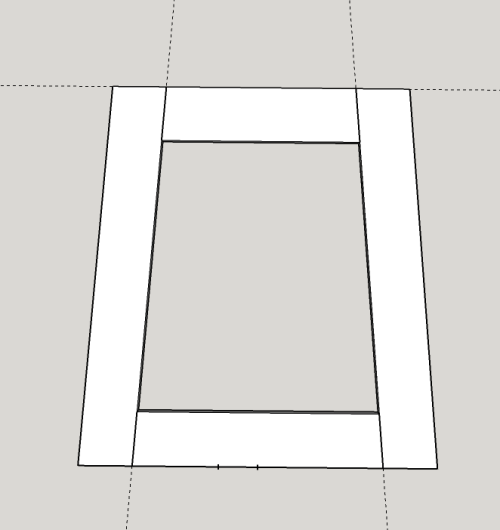
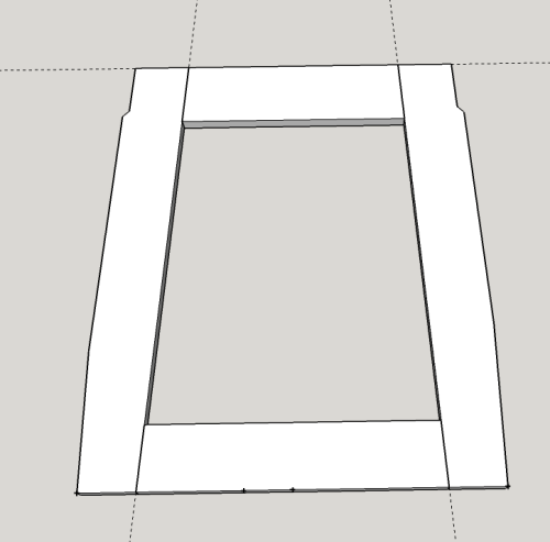
I looked at a number of images online...checked out SketchUp warehouse for some models...purchased a set of plans for a Mission dining chair. I began working on a detailed model in SketchUp.
|
 * * |
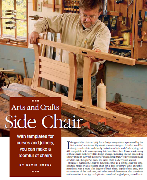
Then, at that time I found a chair that Cindy and I really liked...and the project idea steered immediately to this design. I really liked this Arts and Crafts chair. Kevin Rodel, Fine Woodworking Arts and Crafts Dining Chair Article: FWW #190, March/April 2007 |
|
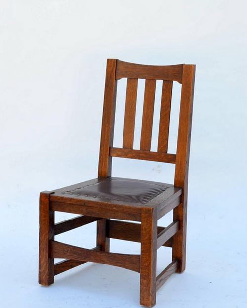
Rodel's chair...oak with leather seat... |
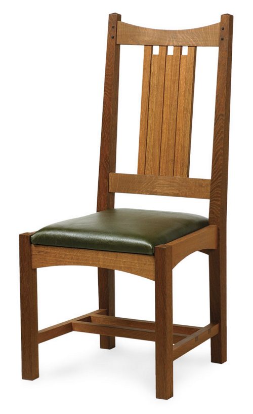 |
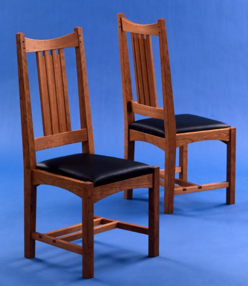
Here is the chair at Rodel's website...in this picture the chair is built of cherry with a black leather seat... |
 |
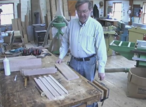
Video
online of Kevin Rodel and the layout and coopering of the splat
assembly. |
 |
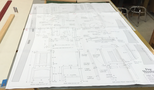
I ordered a detailed drawing... |
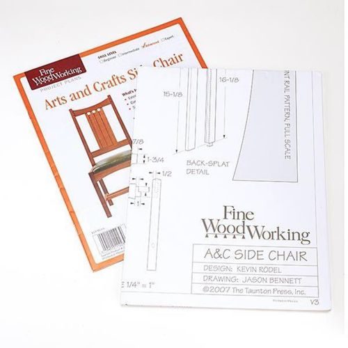 |
The detailed drawing includes scaled down
drawings from multiple angles...this set of plans is 4 feet tall and
3 feet wide. |
 |
I also began a detailed Sketchup of the design. This was a bit challenging...lots of curved shapes, angled joinery, a wide variety of mortise and tenon types...but the CAD drawing slowly took shape...learned some new techniques. |
 |
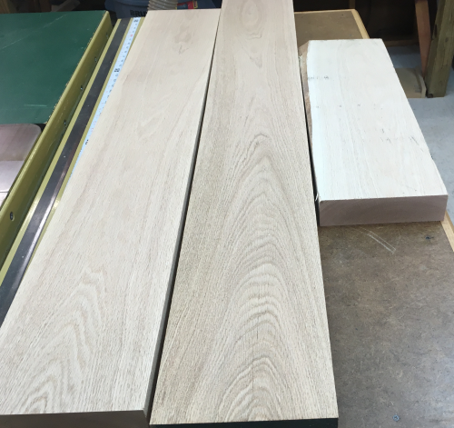
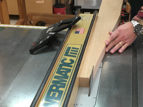
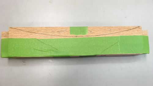
My brother-in-law, Rusty, delivered up some red oak to me. This wood was milled on a farm in south MS and stored in a barn many years ago. The wood is barn dry. Boards were about 12 feet plus, 5 inch plus wide and 6/4 thick. At the Benchmark table, Cindy and I cut them into 6 foot plus working blanks... |
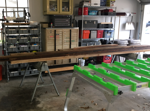 |
...and stored them to surface dry, it had
rained the day they were delivered... |
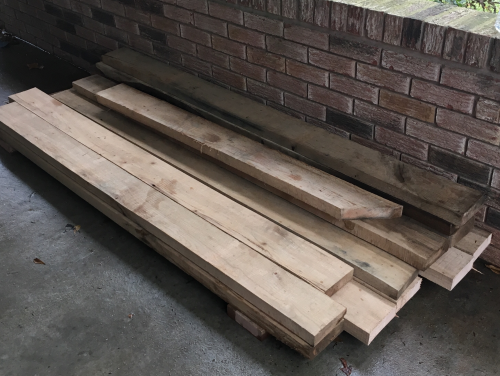 |
...then transported them into the shop. |
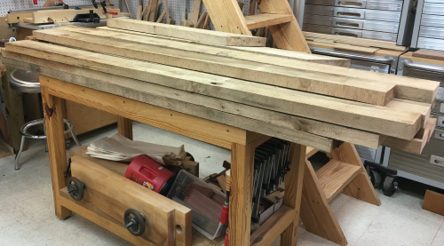 |
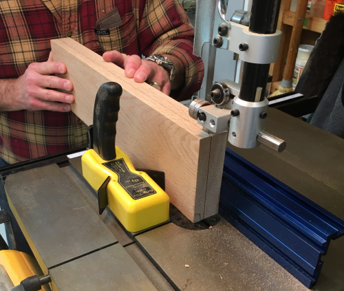
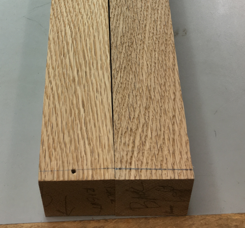
As a test, I jointed a face and an edge
of a cutoff...the boards seem very consistent and I hope to be able
to find pieces that after milling are right at 1 1/2 inches thick to
use for the legs. |
 |
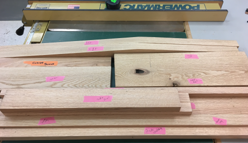
After creating a Sketchup for the A&C
chair...looking at the cutlist it was clear that for some parts we had
to start with 8/4 lumber...the pieces that required the slab were the
2 rear legs, 3 front legs, the crest rail, and the lower back rail. |
.  |
We bought a 8/4 x ~7 inches wide x 9 foot long slab of northern red oak at Pickens...shown are the 5 ft and 4 ft slabs. |
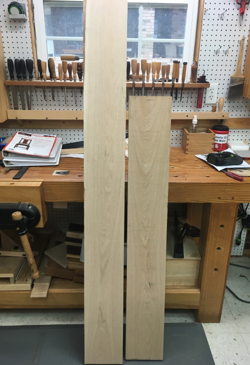 |
Cut
list from pattern sheet |
 |
 |
|
The Rodel chair plans included full scale
images of the items that parts that require templates. |
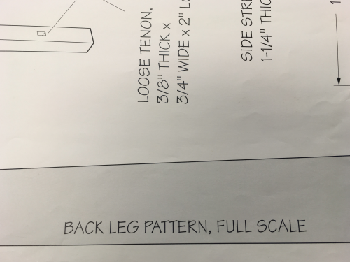 |
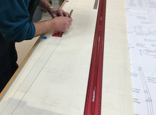
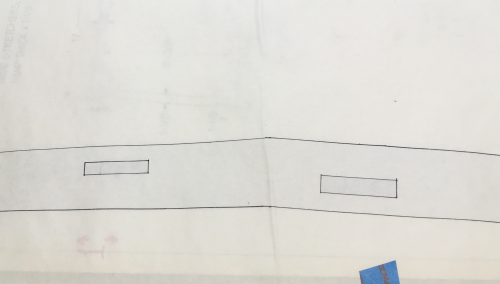
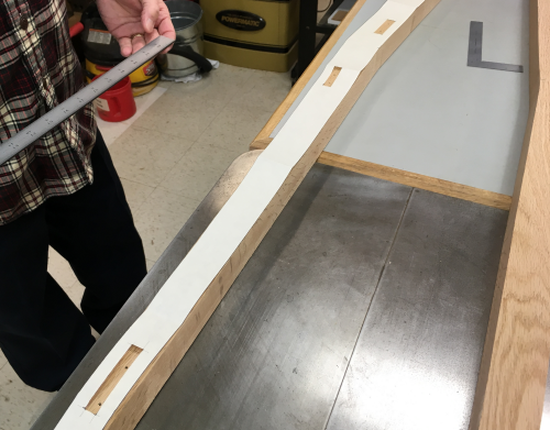
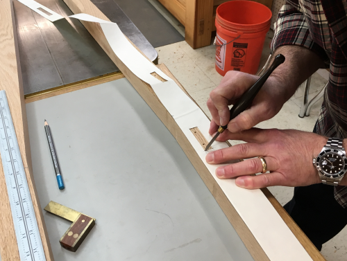
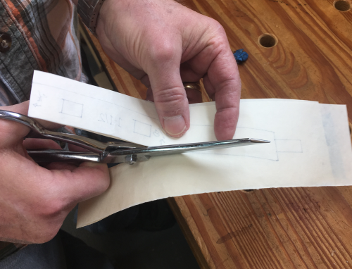
The most important of these templates is
for the rear legs. We taped down the plan and put some butcher paper
over the drawing. Using a .5mm Sakura Perma pen we traced out the full
size template drawing. |
 |
This included the locations of the mortises. |
 |
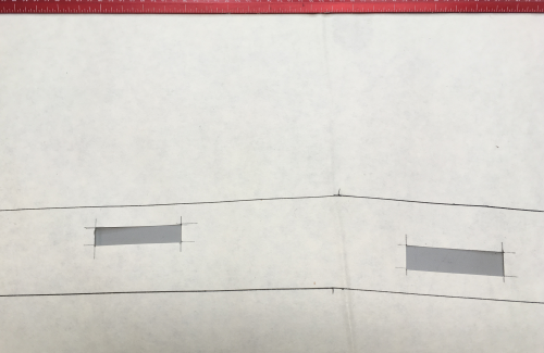
The leg and the mortise layouts were cut
out with an Exacto blade. |
 |
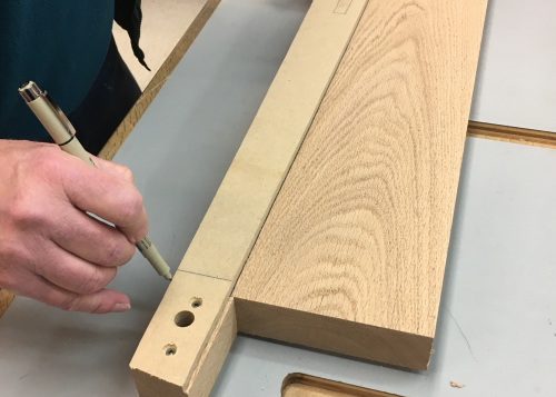
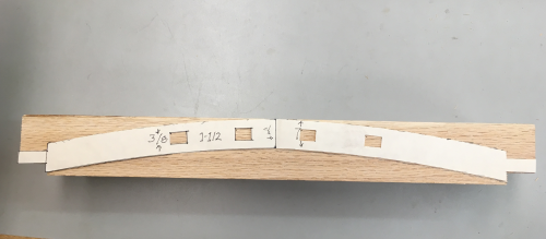
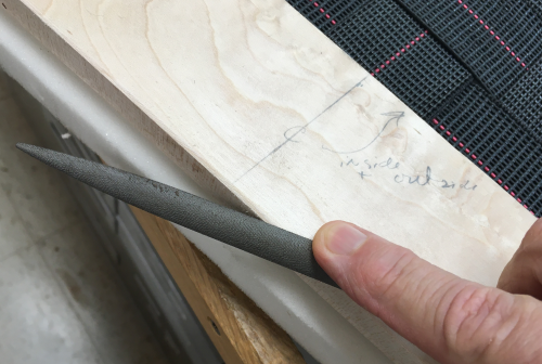
The paper template was laid onto .25 inch thick MDF and the 43" (plus 6" for extensions) outline was applied to the MDF. There was an extension included at both ends to allow for the template jig construction.
|
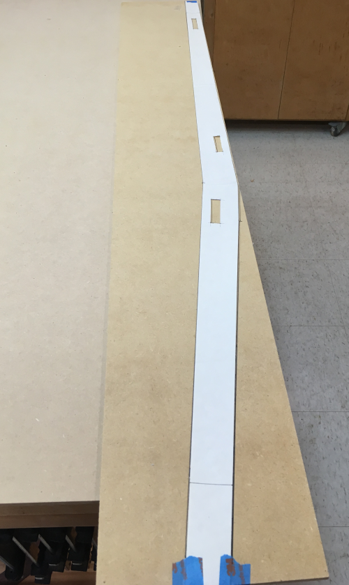 |
The MDF template, which was the pattern
for the right rear leg, was cut at the bandsaw...we it cut a little
fat. |
 |
The template was then sanded down to the
line at the Rigid belt sander. |
 |
The second template (right rear leg) was
jig sawed fat on all sides... |
 |
Then the right template was secured to the
left, fat template with double sided tape... |
 |
...and then the exact copy was routed. |
 |
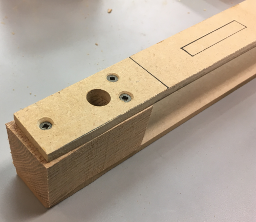
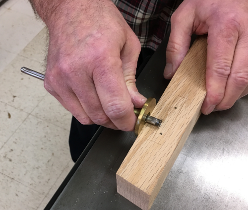
The 1 1/2 inch slab was put into the template
sandwich...a 1/2 dowel hole was drilled...this will be used to index
the templates. |
 |
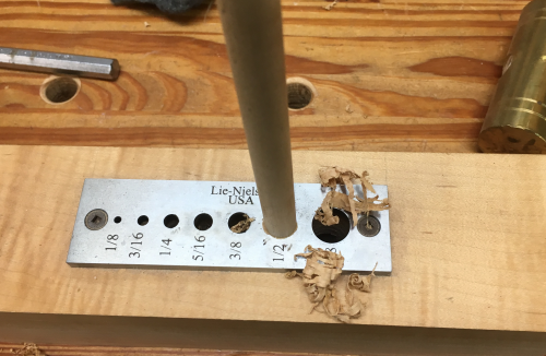
A hardwood oversized dowel was cleaned up
in the LN dowel plate. |
 |
What the template sandwich looks like...the
mortise lay out shows where the template may be screwed down to the
oak blank. |
 |
|
|
|
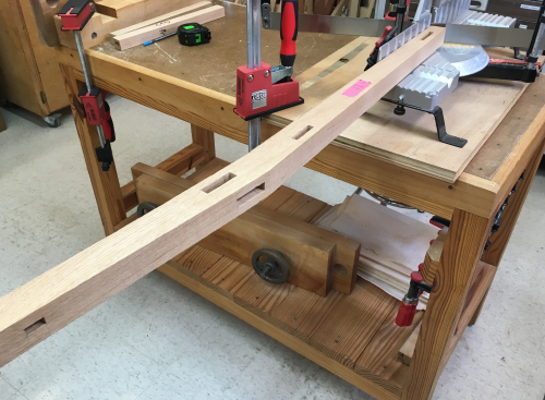
Th 8/4 slab was jointed and planed down
to 1 7/8 thickness for the back rails...and then down to 1 1/2 inches
for the rear and front legs. |
 |
The rear leg blanks were laid out in the
template sandwich...the outline was drawn off to maximize grain runs... |
 |
The blanks were trimmed fat at the bandsaw...had
to use wedge to hold kerf open. |
 |
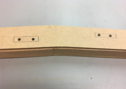
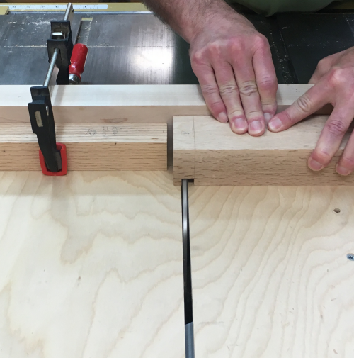
One of the templates was secured to the
blank with screws (SD #6, @ 1")...in the areas of the inside face
where the mortises will be located. |
 |
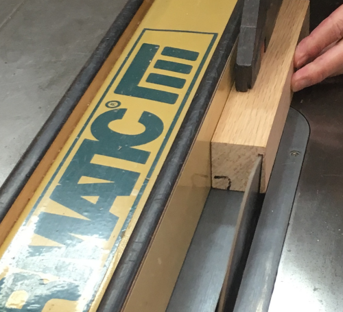
At the router table, router RPM was set down one click off highest...we used a Whiteside spiral combination bit with bearings...a compression bit...up/down spiral. We removed the top bearing...cutting surface is 1 1/8 inches.
|
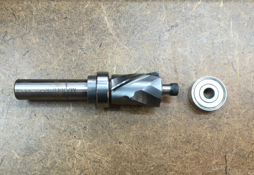 |
The bearing height was dialed in to that the bearing against the 1/4 MDF template at the bottom...this is the template that was screwed down to the blank. Since only one of the templates can receive the screws...It is important to confirm that the bearing is resting against the secured, screwed template. |
 |
Pic after the first pass...the surface is flush with template up 1 1/8 inches...then bit was raised so that the bearing ran against the new surface up to the proper height to finish off the flush cut. Stopped short of contacting the top MDF template... |
 |
The milled rear leg blanks...and the template
sandwich. |
 |
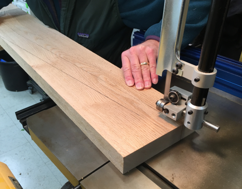
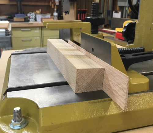
The front legs are 1 1/2 square...here the
blanks are ripped from an edge that was rift sawn... |
 |
This slab is ripped at band saw...the two
different thicknesses of splats (thickies = 5/8, thinnies= 3/8) will
be milled from this piece... |
 |
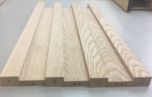
All of the rough billets...planed to appropriate thickness...
|
 |
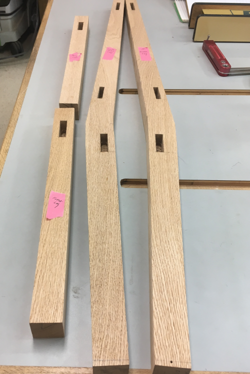
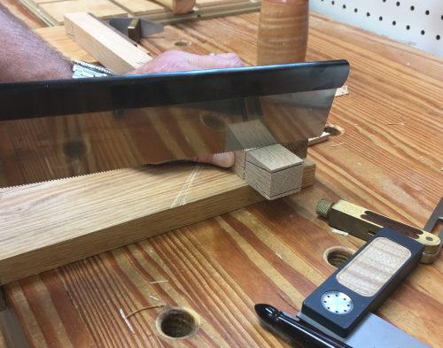
First joinery work will be the rear legs...first layout was the three mortises on the inside edges. We got out the paper template and oriented all locations and surfaces. Of great importance...must make sure that all reference surfaces are identified. |
 |
The layout scribes of the ends of the mortise were were roughed in with a marking knife. |
 |
Then the longer edge mortise layouts were
make with TiteMark from the proper reference surfaces. |
 |
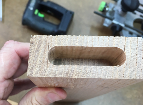
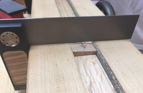
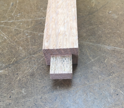
The inner top mortise will accept the crest rail tenon, although the rail is curved the tenon is square to the leg framed. The tenon is milled 3/8" thick by 7/8" long..,and the width will be 2.25 inch. So the upper, inner mortise will be scribed 1/2 inch off the front surface of the leg. The second scribe is 7/8"off the front surface of the leg. This is a 3/8" wide mortise. |
 |
The middle inner mortise accepts the tenon on the end of the curved lower back rail. This tenon is also 3/8" thick and 7/8" long. However, it is not as wide...only 1 3/4". This mortise is also miilled perpendicular and the scribe procedure is the same as above...1/2" off the front, then 7/8" of the front. |
 |
The lower, inner mortise accepts the haunched tenon of the back seat rail. This tenon is thicker, 1/2 inch x 1 inch long x 2 inches wide. The first scribe cut is made at 1/2 inch off the back surface and the second is at 1 inch off the same reference point. |
 |
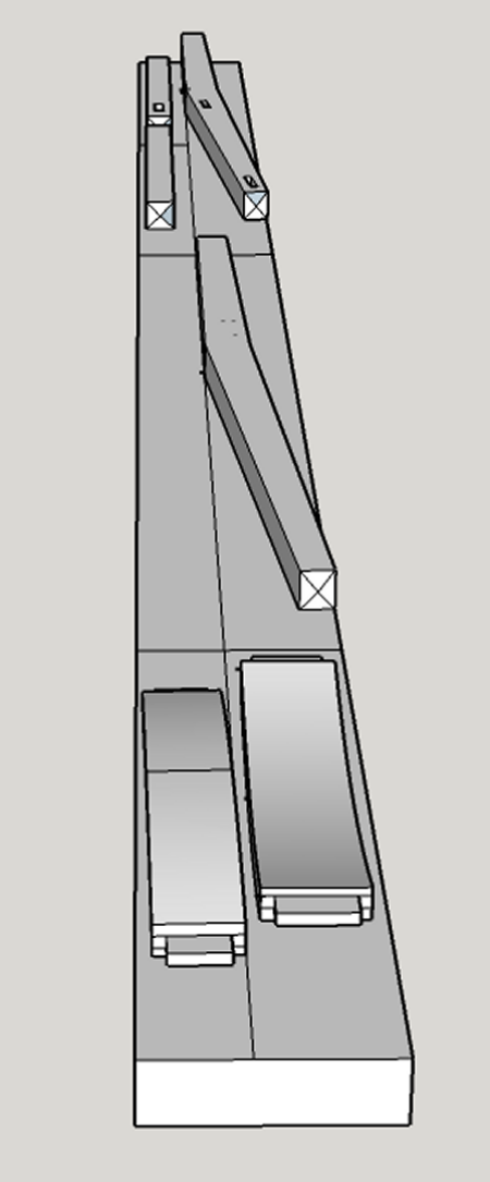
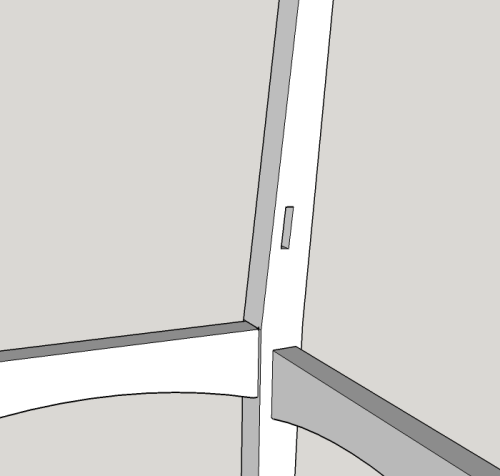
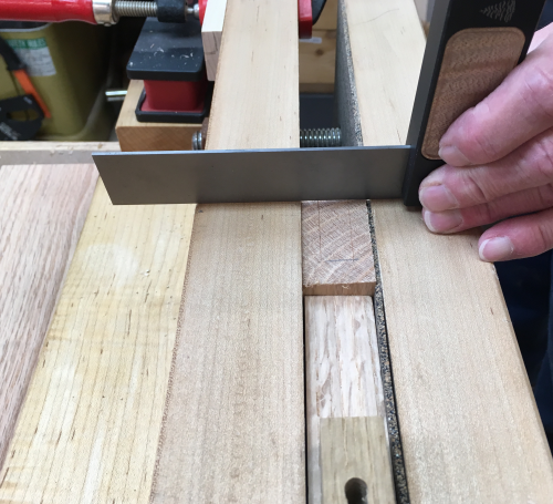
The two mortises on the front face of the rear legs are laid out normally, but they will have to be mortised on an angle of 4.5 degrees... ...this top view of the seating area shows the angles. |
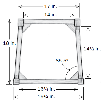 |
The different angles of the faces required careful markout... |
 |
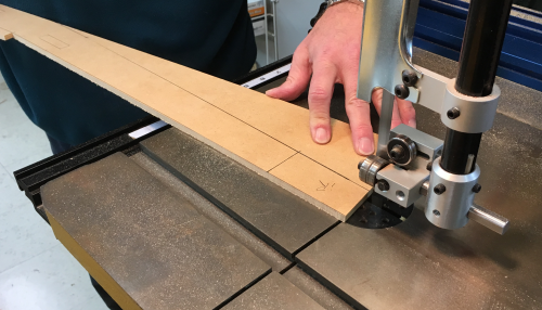
The lower section of the back legs will
need to be trimmed...the cut line was determined... |
 |
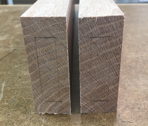
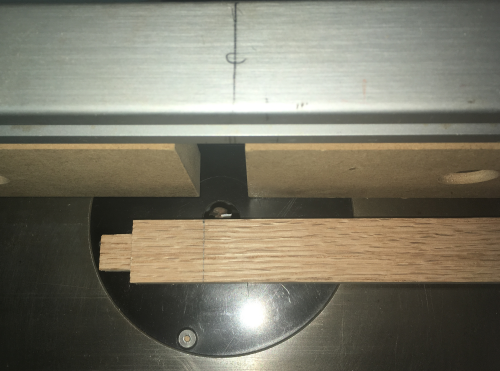
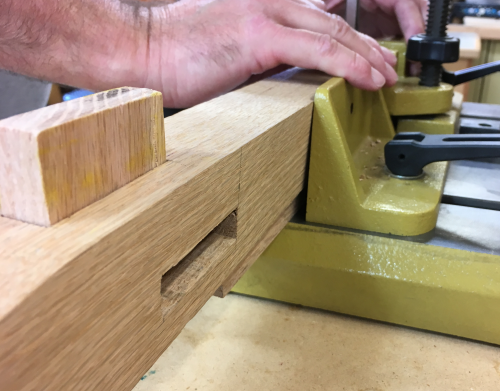
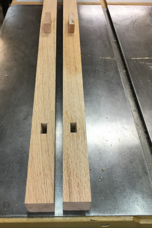
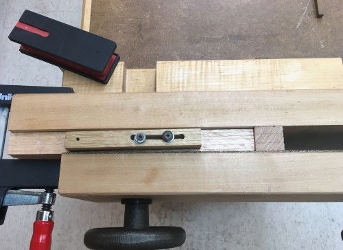
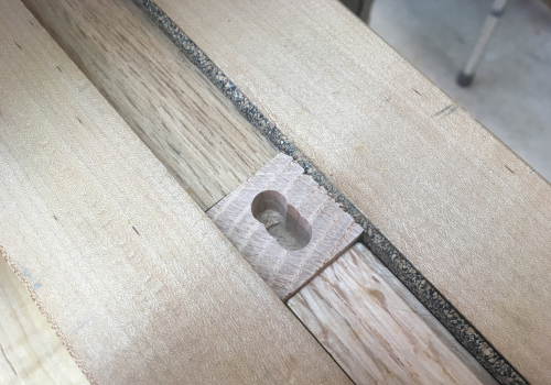
The lower mortise which will accept the floating tenon of the side stretcher are not centered in the leg stock...we pulled 5/8 inches off the outer face of the leg...and then 1 inch off the outer face of the leg...making a mortise that is 3/8 inch wide...the end scribes were pulled at 4.25 and 5 inch so that the length of mortise is 3/4 inch.
|
 |
The upper mortise is centered, also to be drilled at an angle, it will accept the floating tenon of side seat rail...we pulled 1/2inches off the outer face of the leg...and then 1 inch off the outer face of the leg...making a mortise that is 1/2 inch wide...the end scribes were pulled at 15 and 17 inches so that the length of mortise is 2 inches. |
 |
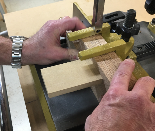
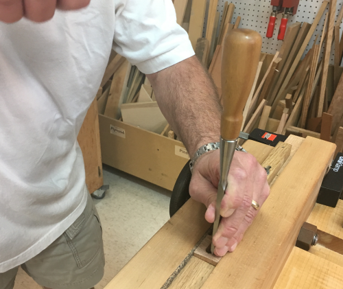
The mortises were milled at the PM mortiser...the easy mortises in this phase are the ones that are perpendicular...we started with the low hanging fruit. First was the 3/8 inch mortises on the inside face of the rear legs...they will accept the tenons on the crest and lower back rails. These were milled to 7/8 inch deep. The mortises were set up at 1/2 inch off the front of the leg. |
 |
The four 3/8 inch x 7/8 inch deep mortises for the rail tenons. |
 |
Then the 1/2 inch mortises...these the lower inside leg mortises...they will accept the tenons on the back seat rail. The layout of these mortises is shown at the bottom of the image above. These mortises were one inch deep. These mortises are referenced at 1/2 inch off the back surface of the rear leg. Because of the angles involved, it is not possible to position the surface square against the fence...so we had to use a spacer because of the angled offset of the leg.
|
 |
| The 1/2" mortises on the front legs were pretty straightforward...1 inch deep...
...all the milled perpendicular leg mortises shown here.
|
 |
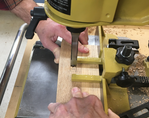
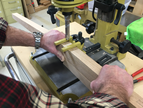
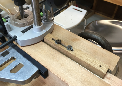
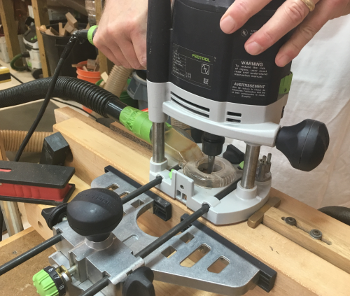
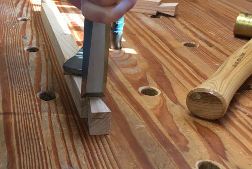
Next we moved on to the more challenging elements...working with non-perpindicular mortising... Working with the rear legs, there was no square refererence surface...so the work piece had to be supported and then squared up to the mortise chisel...this was accomplished using a shim until the calibrated eyeball called it perpendicular...depth was set here as well. |
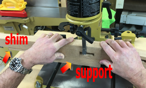 |
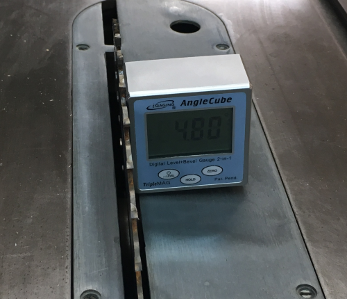
Then we had to wedge the work piece to tilt in toward the mortise chisel...this must be tilted by 4.5 degrees ...so we made a support block to provide this angle...set blade angle with iGuage AngleCube.
|
 |
...and cut that 4.5° at the PM66... |
 |
Then used that block to support and tilt in toward the chisel. |
 |
The 1/2 inch tilted mortises on the longer rear legs were thus supported and altered in two planes and then chiseled to a depth of 1.5 inches. James held the work piece firmly against the block, shim and fence...this took both hands. Thus, it became a three handed operation...I performed the handle pulls. |
 |
The 1/2 inch tilted mortises on the front legs were much simpler. Since the legs were square, they only had to tilted in one plane... we also mortised the 3/8 lower angled mortises on the legs. |
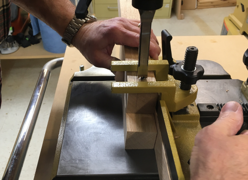 |
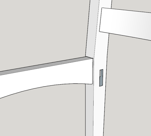
There was some minor tear out when the two mortises met...we put in a dummy tenon and this minimized the spelching. |
 |
All six front leg mortises are finished... |
 |
Joinery Milling |
|
Next we worked on the side seat rails...these will have perpendicular mortises to accept the floating tenons...but the ends of the rails are angled at 4.5° First the 4.5° angle cut at the PM66 using a sled... |
 |
Then flipped the board end to end and used the miter gauge with a stop in order to form the parallelogram. |
 |
This is what the ends look like...just a skosh off 90 degrees... |
 |
Laid out the 1/2 inch x 2 inch mortises. |
 |
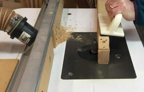
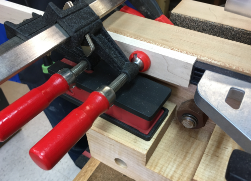
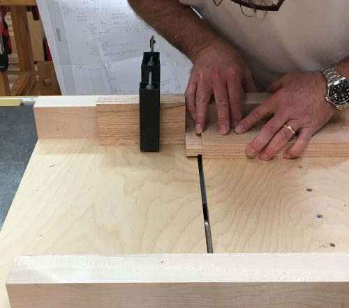
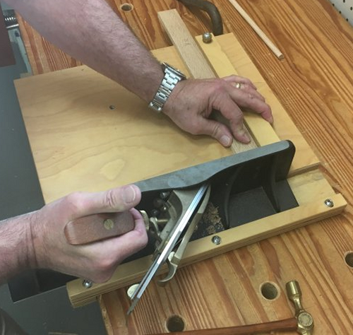
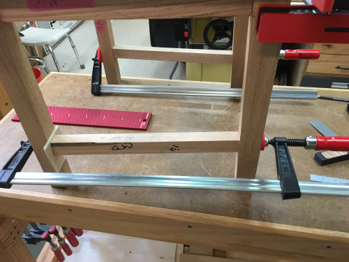
To make the perpendicular mortises in the ends of the rails, we opted to use a router. We secured the rails in the Moxon2 vise and... |
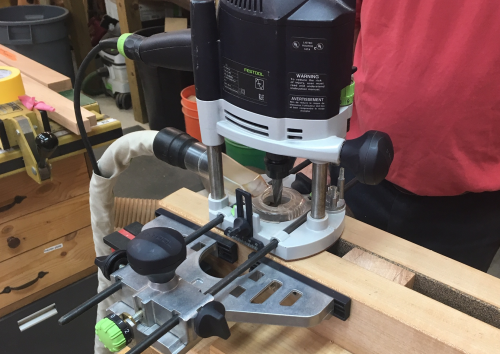 |
...ran a crash test dummy through. Appears that it will work fine...we decided to put in a board to index the board each time...as well as create a end stop for the mortise. |
 |
Used a board slightly thinner than our stock so as to not interfere with clamping...put in a 3/4 hole and extended that to the edge... |
 |
...so that the board will sit down onto the threaded shaft...this substantially fixed the piece at that height. |
 |
| Squared the index board to the vise face...it is slightly below co-planar so that it will not interfere with the router base. |
 |
| Clamped it down...then indexed the work piece against it...will work well. |
 |
We made sure that the top slanted lip was
co-planar with the vise faces... |
 |
Added an adjustable stop at the end of the
right to left routing run...it makes contact with the base of the router. |
 |
Then we located a stop to control the beginning
of the routing run...this stop makes contact with parallel edge guide
assembly. |
 |
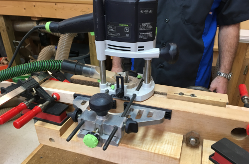
Had to move the Festool vac to the opposite
end of the shop...here is the full rig...it took a long time to get
it set up...it only took minutes to the make the four mortises...triple
pass for the depth...the Whiteside up spiral 1/2 bit was killer. |
 |
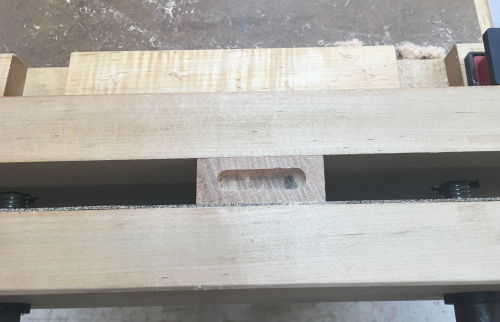
The finished product...a 1 inch
deep mortise that is perpendicular on a face that is angled...stops
were dead on... |
 |
Joinery Milling |
|
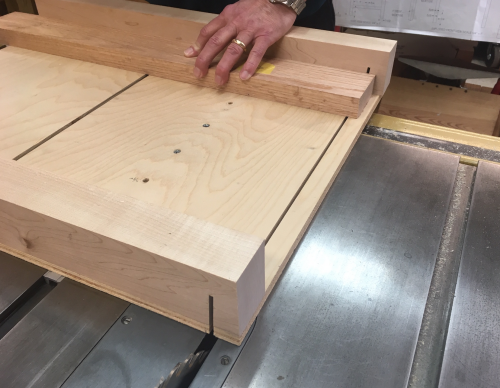
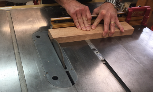
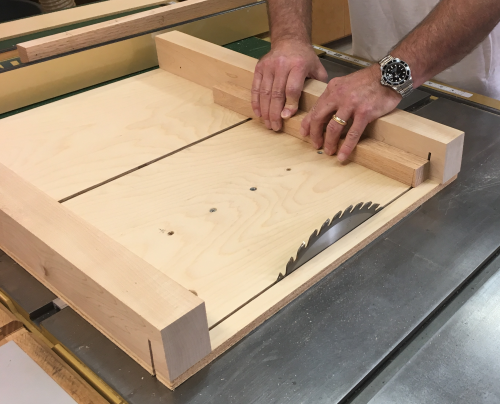
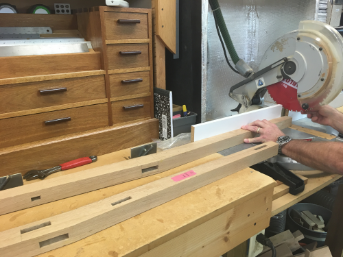
The front and back rail blanks had to have perpendicular tenons at each end...did this at the P66 with 1/4 Infinity blade and using the dedicated sled. |
 |
Front and back rails with tenons... |
 |
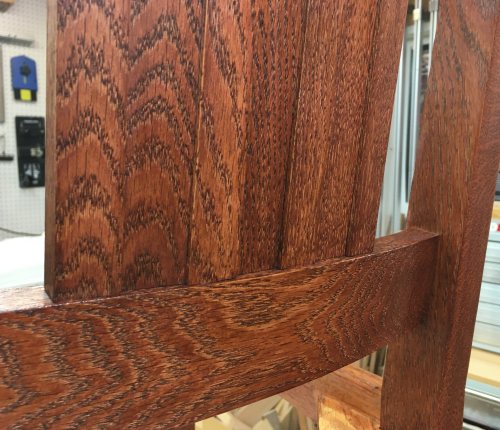
The front and back rail tenons have to have a haunch in order to intersect properly with the slanted leg mortises. The amount of wood to be removed can be seen in this image. |
 |
Haunches were made with hand saws and chisels... |
 |
After
the haunches are cut... |
 |
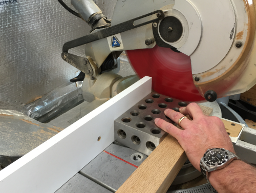
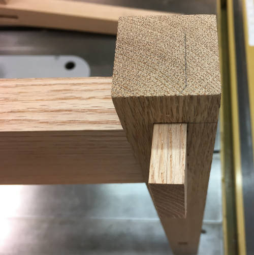
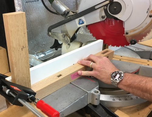
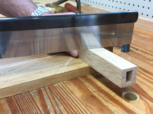
The rear legs had to be chopped to length...and the cut had to be referenced square to the back edge of the leg...which was difficult to do with the angled leg. We used a 2-4-6 block to register square against the chop saw fence. |
 |
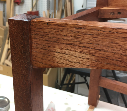
Front legs and front rail dry fit... |
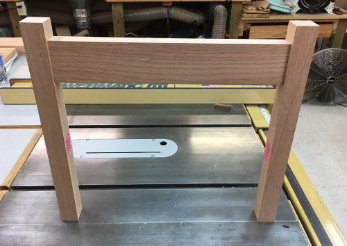 |
Front section...reverse side... |
 |
Close up of floating tenon in angled mortise...front
leg. |
 |
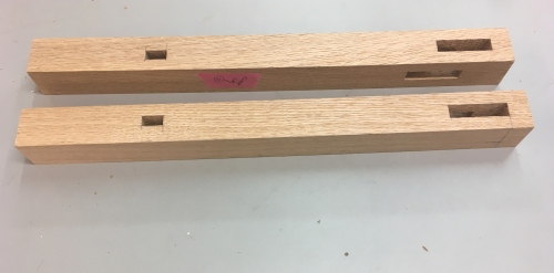
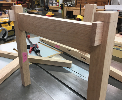
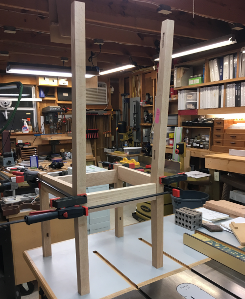
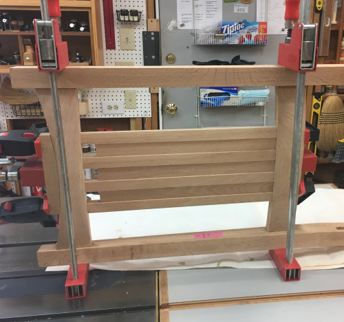
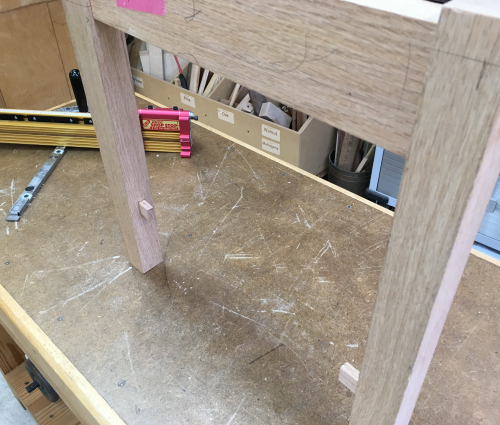
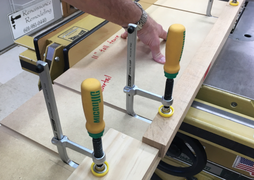
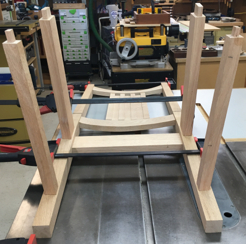
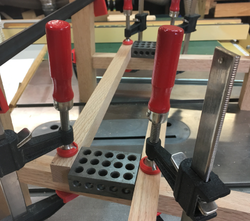
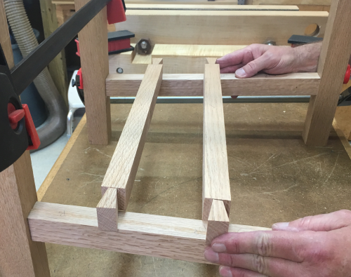
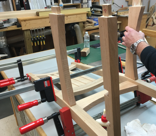
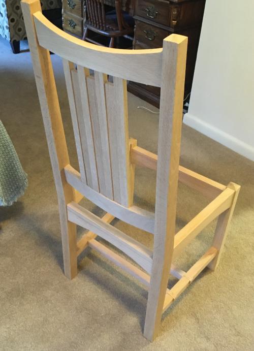
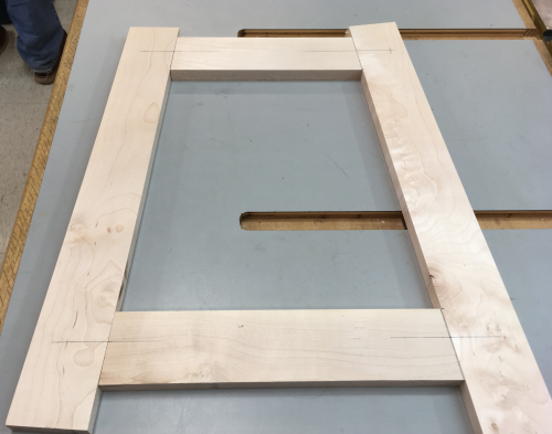
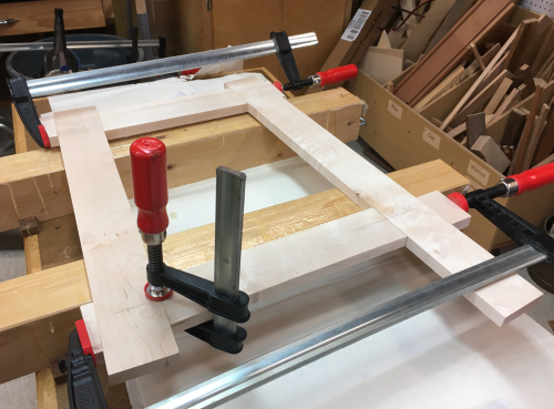
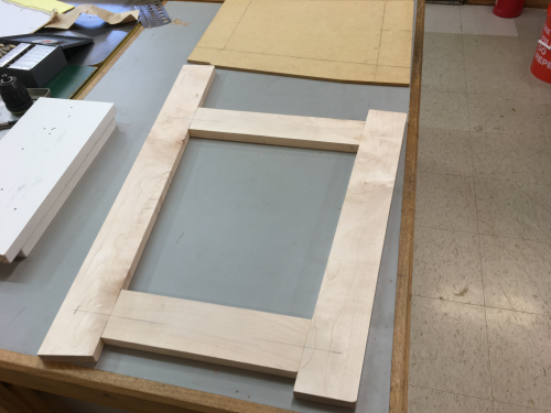
The rear legs, back rail and side rails all dry fit and clamped with the front assembly...all joints looked great. |
 |
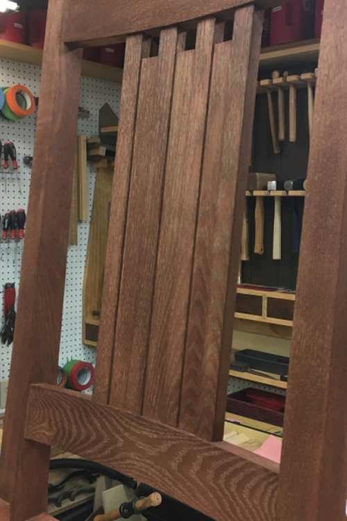
All of the work that we have done so far never gave us much of a hint as to how the finished product might actually look... ...this now looks like a chair. |
 |
There was no wobble at all...everything
lined up well. |
 |
Joinery Milling |
|
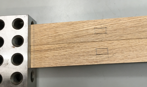
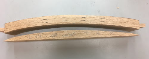
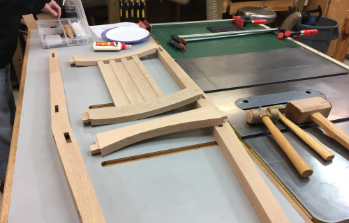
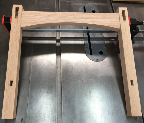
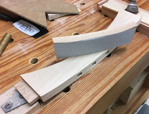
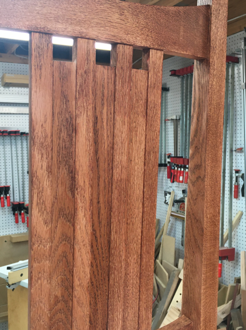
Made a paper template for the curvature cut of the crest and lower rail. |
 |
Using the template, we were able to visualize the curved cuts, the end tenons and the eventual mortises to hold the splats. |
 |
| After ripping and chopping the blanks, the tenon ends were milled using the 1/4 Infinity blade and the dedicated sled. Face of the show side tenon was milled at a depth of 3/8 inch, will later be ~1/4 inch. |
 |
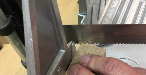
The waste removal to form the back side of the tenon was done with a handsaw...the Stilleto rocks. |
 |
Second cut...easy using the cheeks already defined with Infinity blade... |
 |
The finished tenon. |
 |
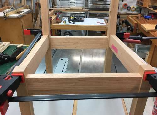
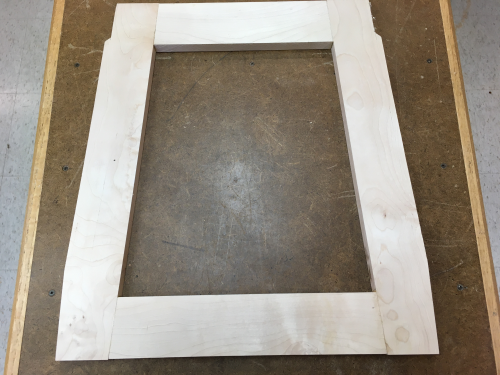
Dry fit of the crest rail, lower rail and back rail...really looks like a chair... |
 |
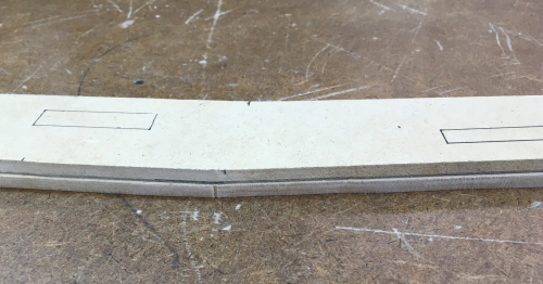
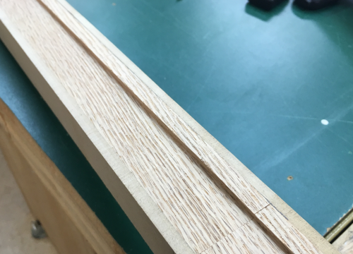
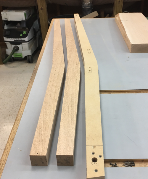
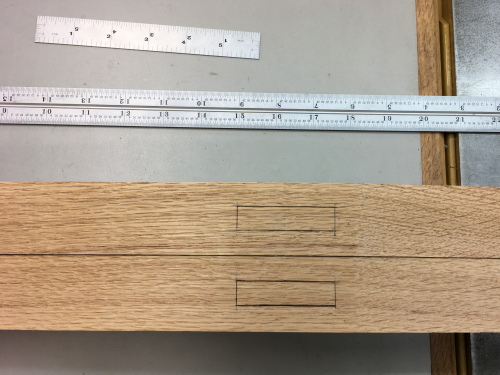
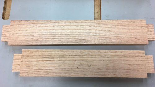
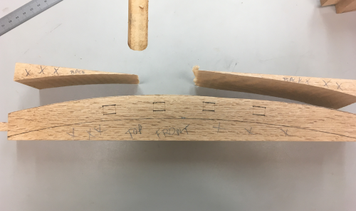
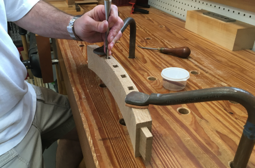
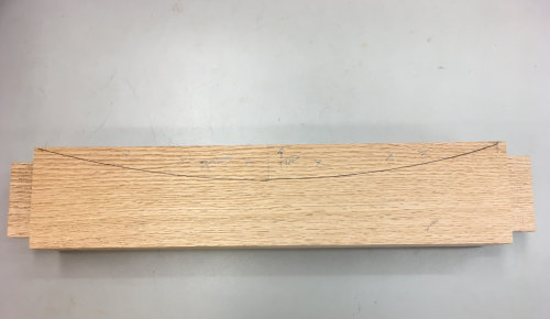
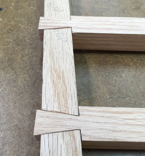
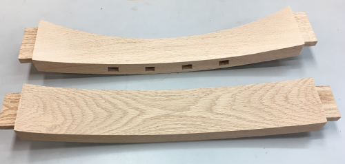
The blanks for the crest and lower rails had to be laid out for the front and back concave & convex cuts...plus the four mortises. This view of the bottom edge of the crest rail... |
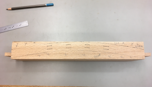 |
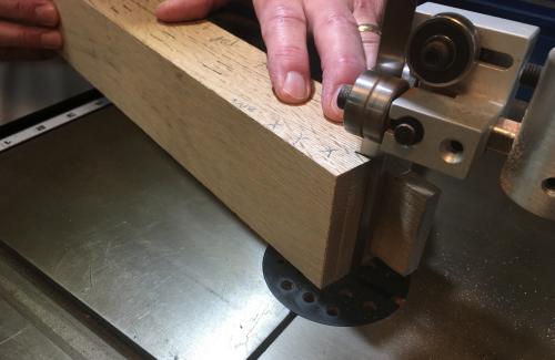
The first cuts at the bandsaw were to take off the two smaller arcs at the back...this cut is on the lower rail. |
 |
The backside arcs...material removed...this image is the upper face of the lower rail. |
 |
...the second bandsaw cut is the convex arc on the front side... |
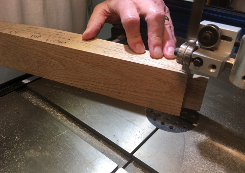 |
...front material removed. |
 |
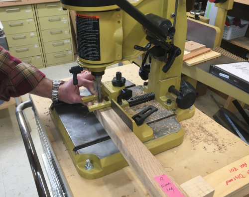
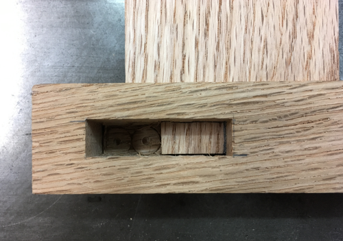
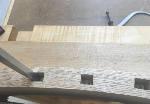
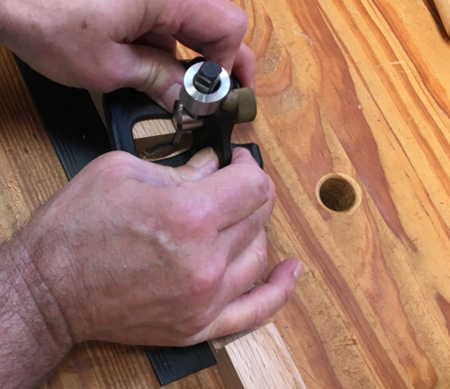
Then the arc backsides were registered against the fence on the PM mortiser...and a 3/8 inch mortise bit plunged 1/2"...there were four mortises on both the bottom edge of the crest rail and the top edge of the lower rail. |
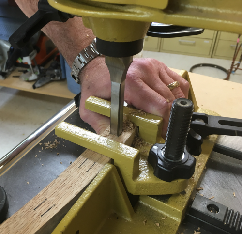 |
The four mortises were cleaned up with chisels... |
 |
After cutting off the concave front of the crest rail, we had to cut off the top concave arc... |
 |
...the waste arc of the concave front was then taped back onto the blank... |
 |
...and cut at the bandsaw. |
 |
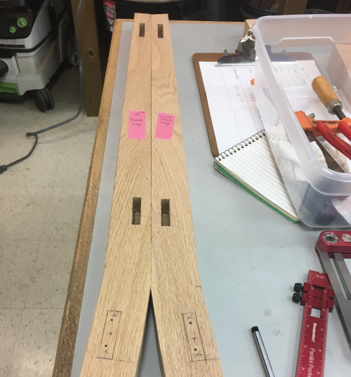
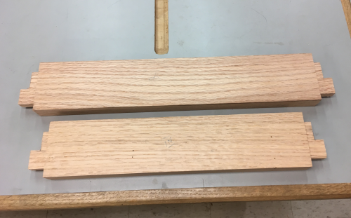
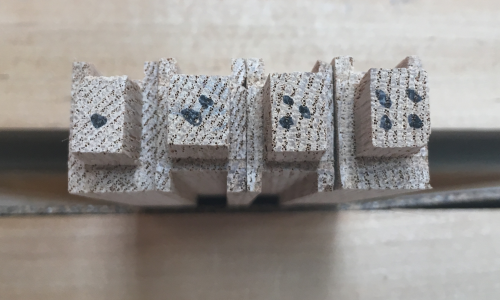
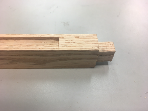
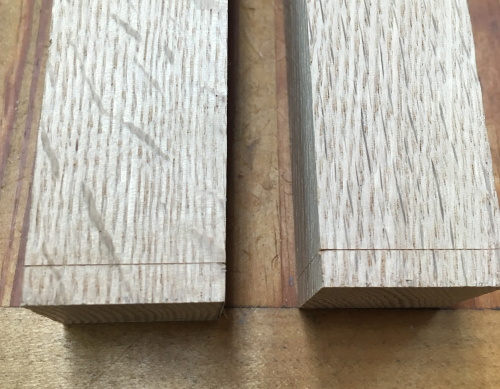
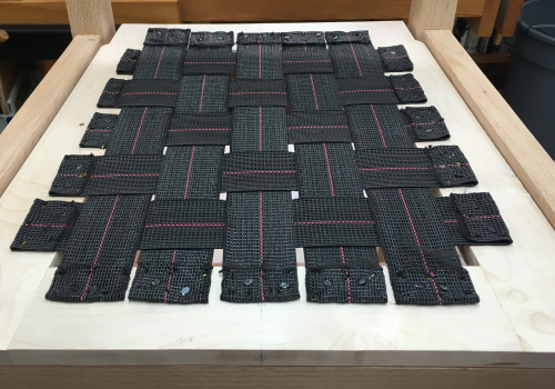
Splats...the milled blank for the thicker (5/8") splats was minutely too skinny...had to recalculate width of the longer, thicker splats...made it a 1/16 less wide (15/16 in.)... we then increased the thinner (3/8") and wider splats by 1/16" We paid some attention to the grain and declared these ends as the bottom of the splats.
|
 |
The length of the 5/8" splats were milled a hair fat at 16 7/32 shoulder to shoulder with 1/2 inch tenons on each end... The wider splats will not have tenons. |
 |
After the tenons were milled...we chiseled
out the mortises on the two rails... |
 |
...final fits on tenons with shoulder planes. |
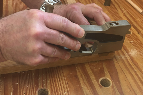 |
A successful dry fit for all mortise/tenon joints...used a cut-off as a clamping caul. |
 |
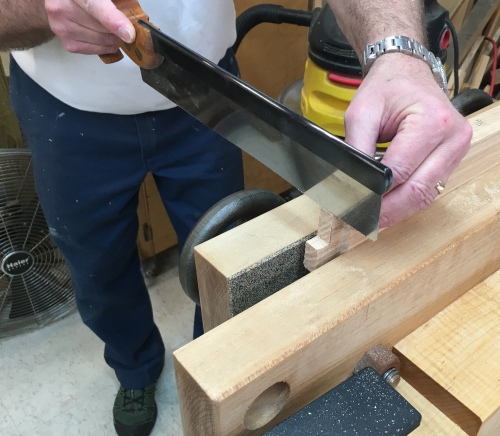
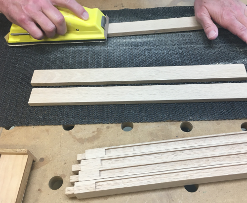
The top show edges of the 3/8 inch splats were squared off to length with LN51 @ shooting board. |
 |
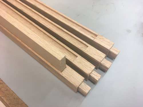
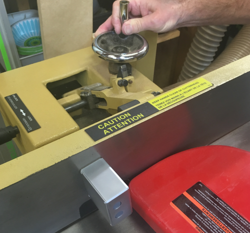
The sides of the 5/8" splats are stop grooved (3/8" wide x 1/8" deep)...grooves made with up/down spiral bit at router table...drop down start was short of line and will be chiseled to fit later. |
 |
Starting at the top, the stopped groove
edge was dropped onto bit... |
 |
The outside splats were grooved on one side...the
inner splats were grooved on both edges. |
 |
...the gaps at the top after grooves... |
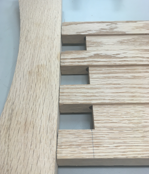 |
...the gaps at the bottom after grooves. |
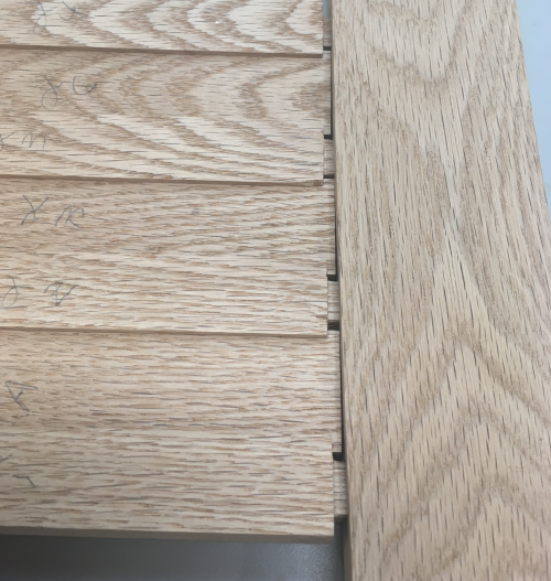 |
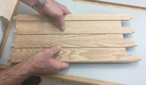
After chiseling the square ends of the stopped
groove... |
 |
...dry fit went well... |
 |
Spacer splats got 2° bevels put on both sides toward show face...this simplifies the postioning of the spat assembly to align with the curvature of the rail arcs. Angle set at PM jointer with digital gauge showing the 2° angle... |
 |
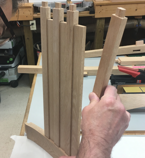
A look at the front dry fit... |
 |
A dry-look at the rear view of the splat assembly...although the 2° taper cuts were barely visible the splats made the curves quite easily. |
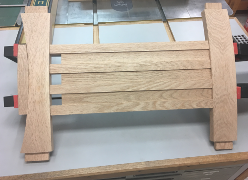 |
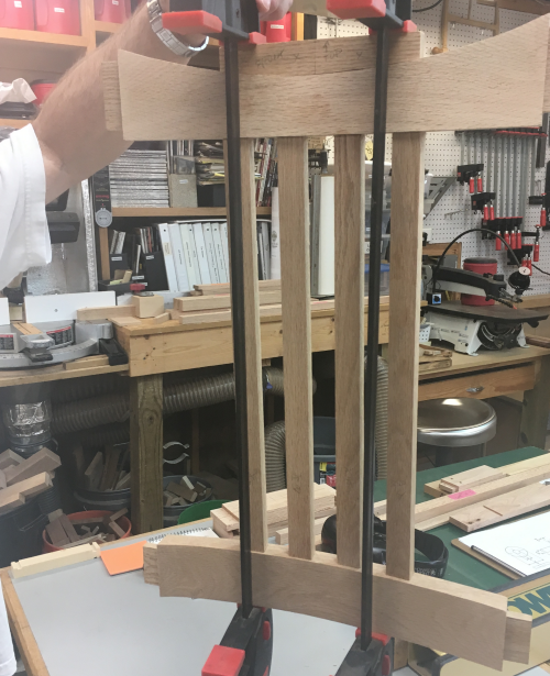
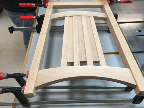
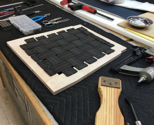
After sanding to 220x, we began the glue up...filled the slots with glue... |
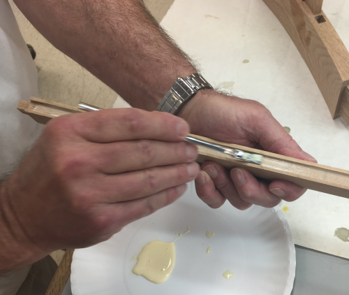 |
Glued the lower tenons into the mortises
of the lower rail...put spacer splats into the grooves... |
 |
Applied clamping pressure to the splat-rail assembly... |
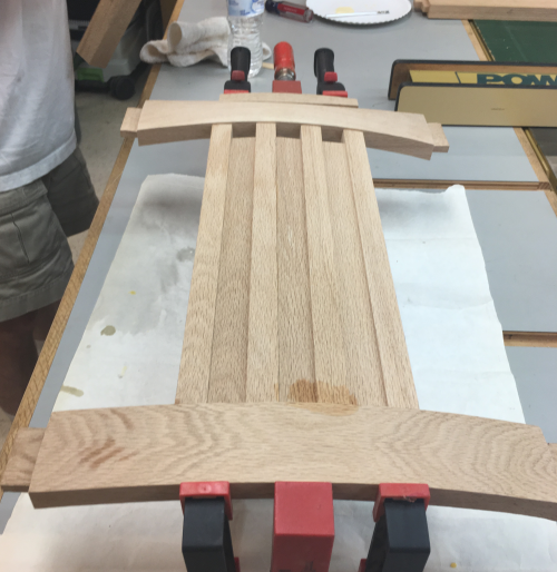 |
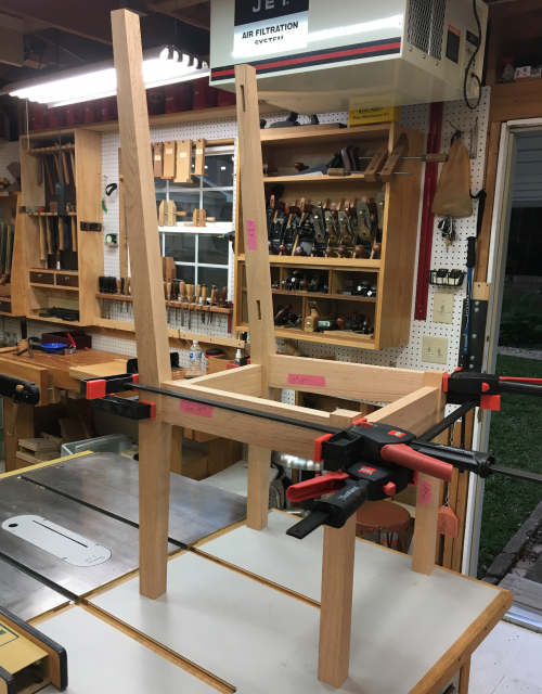
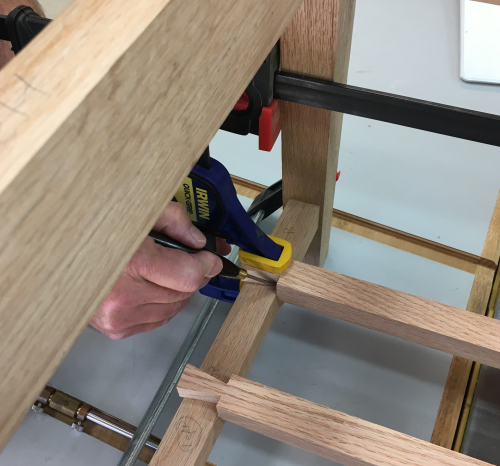
Then dry inserted the assembly into the mortises of the uppler legs...and clamped it all down... |
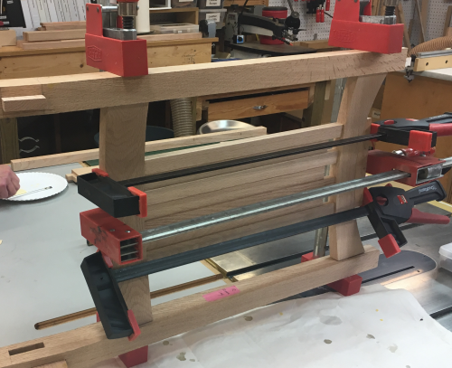 |
View of the back assembly. |
 |
Final Joinery Milling |
|
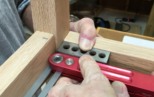
The side stretchers have floating tenons with the mortises on 4.5° The final mortise was milled at PM dedicated mortiser with a long 4.5° shim providing the angle for the mortise. |
 |
The finished back leg mortises... |
 |
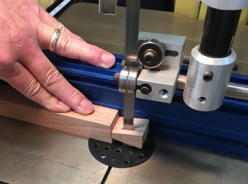
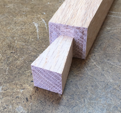
A dry fit of the floating tenons to observe the layout of the side stretchers. |
 |
The front ends of the side stretchers were crosscut at 4.5°...this was done at the PM66 with a crosscut sled... |
 |
The rear ends of the side stretchers received the same 4.5° cuts but a compound angle was required for tight joints...the rear lower legs are not square to the side stretcher like the front legs...the lower edge of the stretcher will have to be longer than the top edge...about 2°... |
 |
So the rear compound angle was cut on the P66 using a mitre gauge...4.5° set at blade...the 2° off of ninety set at the gauge... |
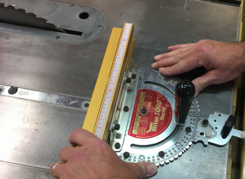 |
...we snuck up on the cut. |
 |
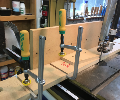
...now to mortise the ends...we set up the Moxon2 like the earlier side rail mortise setup...
|
 |
Router setup...used a 3/8 inch block as a spacer to make the cuts... Had a major disaster using the 3/8 inch up down spiral bit...it burned badly in the oak endgrain...issues with the down spiral causing dust build up in the plunge route stage. |
 |
Purchased a 3/8 inch up spiral...worked
much better...nice clean cuts. |
 |
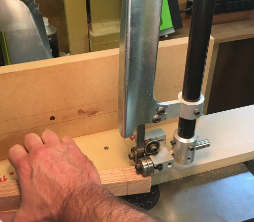
The proudest edge of the compound cut end of the stretcher was made square to the vise. Image shows the amount of the angle... |
 |
Mortise edges were squared with chisel work. |
 |
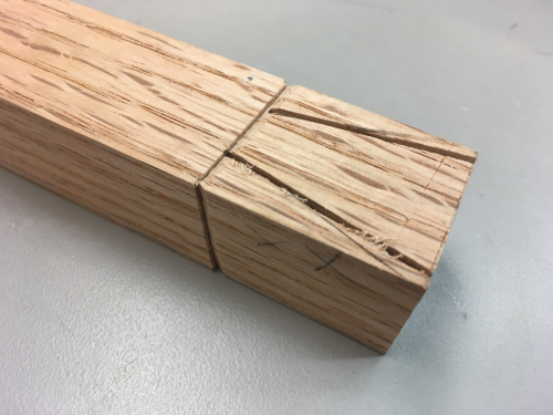
The floating tenon dry fit...all worked well with one small blowout...fixed with glue. |
 |
The rear legs had to be squared off at the
top before continuing...due to the shapes and angles of the rear legs
it was difficult to find square reference for the cut off...we removed
part of the fence at the chop saw so that the back edge of the top portion
of the leg could register square againt the chop saw fence. |
 |
Making the long taper on the outside faces of the legs was also difficult for the same reason...so many different face angles. There was no way that this would set up on the shop built taper jig...but we took a new tall table saw fence (made for MatchFit clamps)...and used it flat down on the top of P66. Image here is the setup to the left of the blade... the setup was moved to the right of the blade for the other leg. |
 |
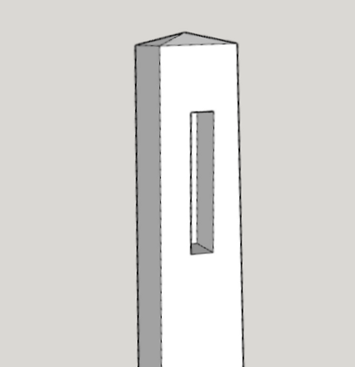
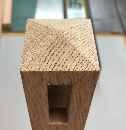
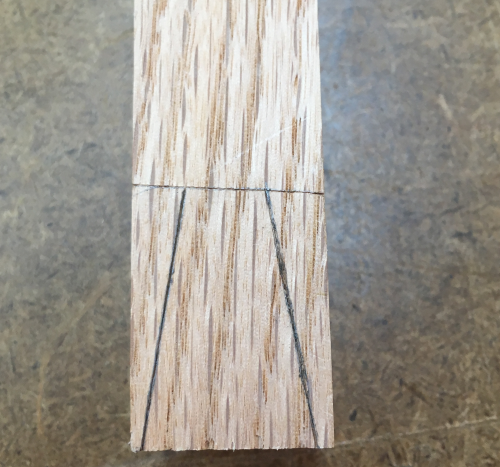
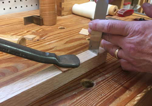
Next came creating the pyramid tops of the
four legs made with chamfer cuts...on the front legs... James calculated
the required angle on the 1.25 x 1.25 inch front legs to be ~22°...set
the chop saw to cut the chamfer 1/4 inch from top...set a stop and cut
all of the faces... |
 |
Finished chamfered pyramid on a front leg. |
 |
On the rear legs, the cuts could not be
made at the chop saw due to the odd, long shapes of the rear legs...here
the ends to be chamfered were marked at a 1/4 inch... |
 |
...then the chamfers were made with the Nobex Champion 180 mitre saw...this was possible due to the small fence. The long leg could be cantilevered as necessary left/right and up/down. |
 |
...the saw has a japanese blade that works
on the pull...worked well on three sides, the last side being difficult
due to flex in the blade. |
 |
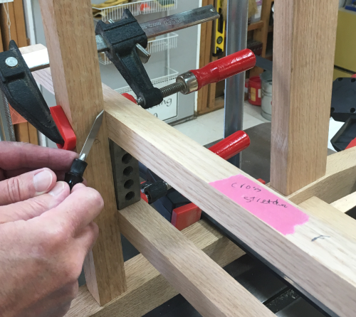
Dry fit before final mark outs...checking
out all of the angled and compound angled floating tenon/mortise joints. |
 |
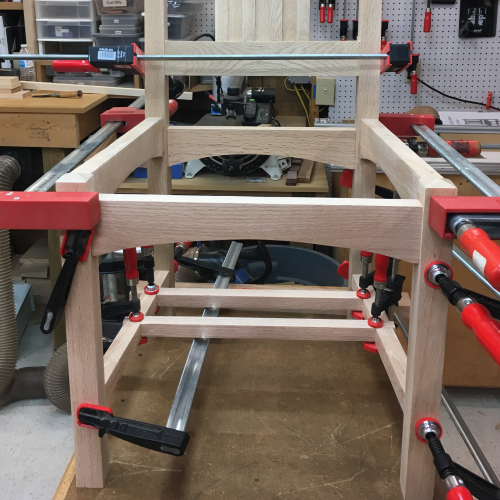
Chair dry fit. |
 |
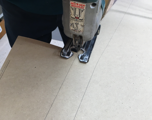
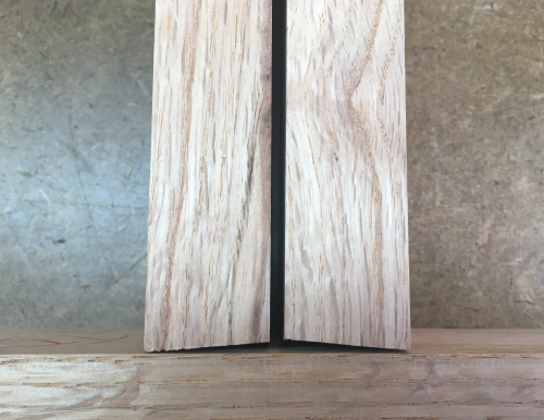
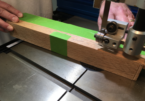
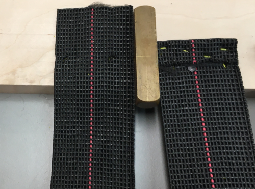
After disassemblying chair, arcs were bandsawn
on the front, back and side rails. |
|
Final Joinery Milling |
|
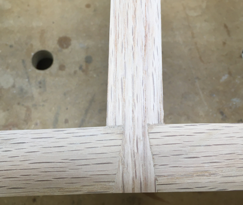
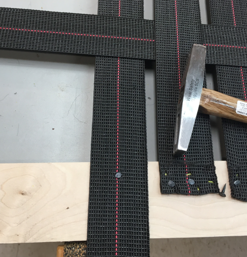
The cross stretchers attach to the side stretchers with a dovetail joint. The stretchers were placed onto the side stretchers at 7" and 10" from the front of the chair. |
 |
The angles were scribed... |
 |
Dovetails were marked off the end...entire length was cut 1/8 inch fat at each end. |
 |
We devised a jig to make controlled cuts at the bandsaw...but first the shoulders were laid out and chiseled to make Class 1 cuts... |
 |
...bevelled edge chiseled in... |
 |
We took a 4 inch tablesaw fence that I had made for MatchFit clamps...laid it flat on bandsaw table, against the fence, then altered it by screwing in an angled plate... |
 |
The end of the cross stretcher was aligned with the front edge of the plate...then the clamps held it in place...the dovetail was cut, piece was flipped, and cut again. |
 |
Bandsaw cuts were stopped at the bevel... |
 |
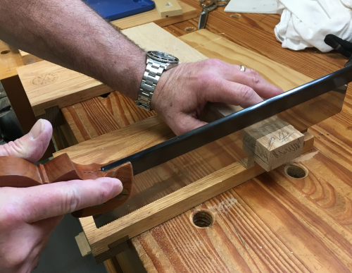
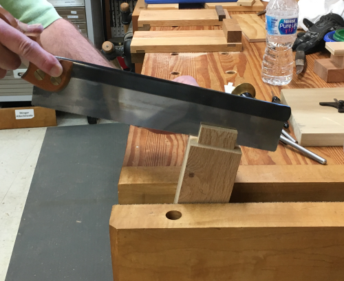
Then the side shoulders were sawn with the Bad Axe hybrid dovetail saw... |
 |
A dryfit of the shoulder lengths...
|
 |
Dovetail socket layout... |
 |
The dovetails were trimmed to 5/8 inch at the bandsaw. |
 |
The shoulders were cleaned up with chisel work. |
 |
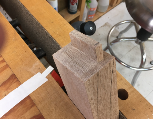
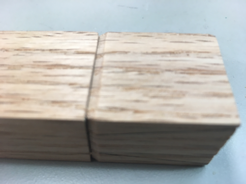
A finished dovetail |
 |
Dovetail socket was sawn by hand (hybrid cut Bad Axe) to a depth slightly shallower than the thickness (5/8 inch) of the dovetail. |
 |
The socket was chiseled out and the depth was set with a router plane. |
 |
Dry fit...the dovetails were cut to length fat and the socket was made shallow...after glue up the cross stretcher surfaces will be hand planed and then sanded. |
 |
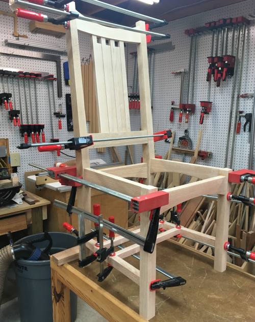
Test assembly...ready to be sanded... |
 |
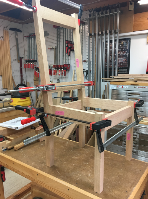
The glue up assembly day...all ready to go. |
 |
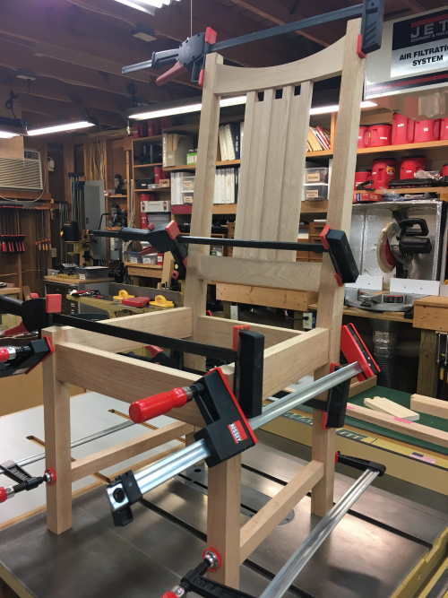
The process started well...we had done a good dry run practice of the full assembly...the back splat unit and the back rail were glued to the rear legs first. |
 |
The the front rail tenons were glued into the front leg mortises and clamped. |
 |
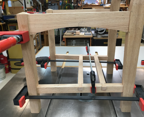
Then the tenons of the side rails and the strechers were glued into the rear legs. |
 |
When the front assembly was attached there was a major problem. The right rail tenon would not seat properly into the right front leg mortise. We tried clamping tighter, clamping differently, etc. and we feared that something was astray due to the compound angles. We were frustrated and time was killing us...glue was setting... |
 |
...then I remembered that we did not double check the length of the exposed tenon after we had glued the floating tenon into the rail...with glue drying, we pulled the front assembly off, determined that the tenon was exposed too far, we chopped it off to proper length...and got everything back together and clamped. Successful recovery. |
 |
After clamps pulled... |
 |
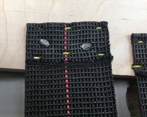
Rear view...only milling and fitting left to do is to make the cross stretchers coplanar with the side stretchers... |
 |
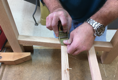
The cross stretchers were left proud...block
plane was used to make them coplanar. |
 |
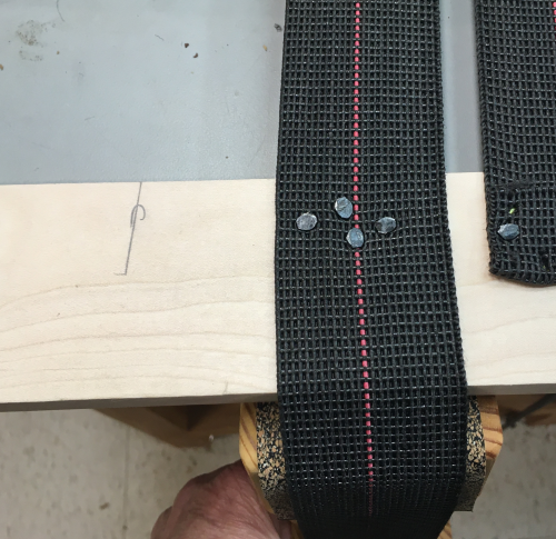
Where joints were not quite tight, we used the "dab and dust" technigue with very fine red oak sawdust and then worked it into the joint... |
 |
...the "dab and dust" works pretty
well except where dealing with end grain...since this was long grain,
after sanding all the joints looked very good. |
 |
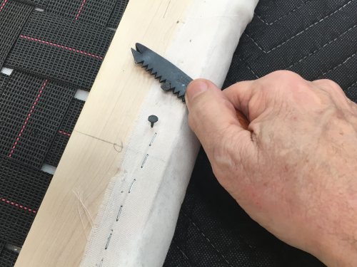
The ends of the dovetails were extended
proud of the side stretchers...they were sawn off with a flush saw. |
 |
End view after sanding with RX90... 120x > 220x > 320x > 400x...
|
 |
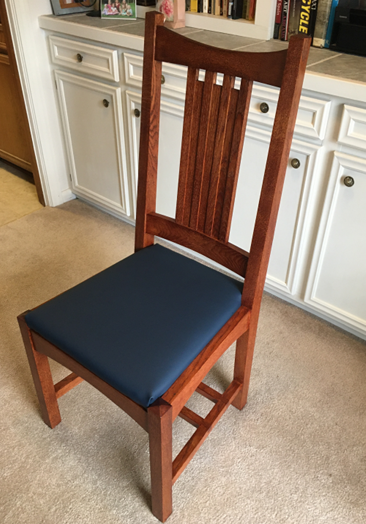
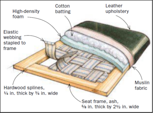
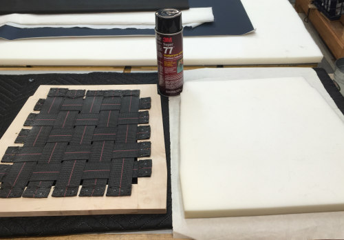
The leather seat is an upholstered slip seat. Rodel gave virtually no information as to how to make the frame or how to upholster it. I researched slip seat upholstery on the web and found many good how to pages as well as videos. After reading and watching many of these I settled on a wonderful series... this was a Fine Woodworking video workshop titled "A Woodworker's Guide to Upholstery with Michael Mascelli". I decided to use this video series as the basis of my upholstery work. Mascelli is a professional upholster and he is an excellent demonstrator. This series is about making a drop-in seat for a Craftsman style rocking chair built by Michael Pekovich. Even though the style of cushion seat is different, most of the installation phases would be quite similar. I had to modify a number of steps based on the tools and materials that I had available to me. Materials, Frame Build, Attaching the Webbing, Cushioning Layers, Vinyl Leather, Frame Installation
|
|
Rodel shows this image as the method of construction and upholstering the seat. |
 |
I have no ash nor is it sold much locally...the seat frame will be maple...
|
 |
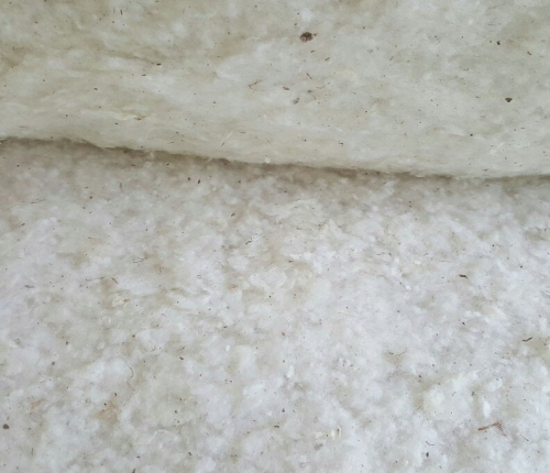
Cotton Upholstery Batting Padding-Sold in Half Yard Increments-Pure Raw Cotton off Etsy.com |
 |
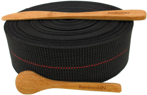
BambooMN Brand - Two-Inch Latex Elasbelt Webbing x 40' Roll from Amazon |
 |
Cambric fabric...dust cover Black Accord local, Woolley Brothers |
 |
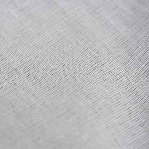
Muslin fabric local, Woolley Brothers |
 |
Whisper vinyl fabric...Navy local, Woolley Brothers |
 |
I will use Dominos in lieu of hardwood splines. |
 |
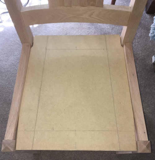
Made a 1/4 thick MDF pattern first... |
 |
The pattern was dry fit into the chair. Fits OK...will need to be careful on the long leg runs...must have some room on the sides.
|
 |
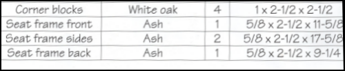
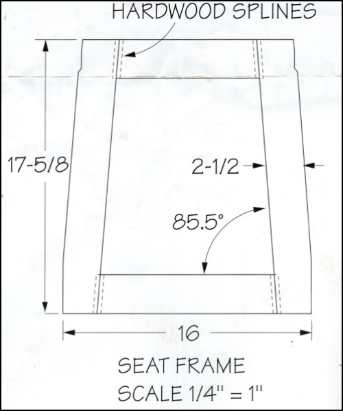
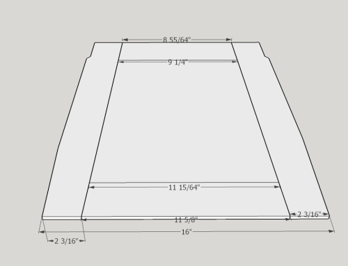
| Cut and mill blanks to be...5/8 thick by 2.5 inches wide by... Front: 11 5/8, trim ends @ 4.5°
|
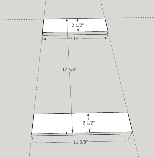 |
The sides will then be tilted to 4.5° and placed at the ends of the with overlap at the top and bottom. The very back edge is 17 5/8 inches from the very front edge. |
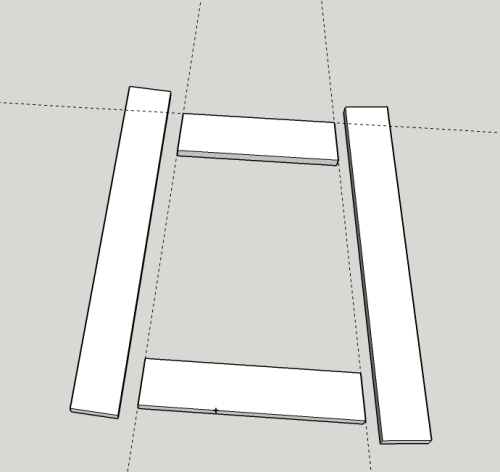 |
The joints will be secured with Dominoes and glued...then the sides will be trimmed to be coplanar with the front edge and the back edge. |
 |
Then at eight inches from the center of the front piece, perpendicular lines are extended up the side edges and cut off. At the back end of the side edges, 1/4 inch is removed to about 2 inches from the back edge...cut in 45° x 1/4 inch. |
 |
The maple pieces were milled from a 5/4 x ~6" x 80 inch slab. After jointing a face and an edge, the slab was planed...then the slats were ripped off @ 2.5 inches. Front and back rails were cut off at 4.5° and then the sides (cut overly fat) and rails were joined with Dominoes (6mm x 40mm).
|
 |
The frame assembly was then glued up...used
the angled cutoffs as cauls. |
 |
Out of the clamps... |
 |
The overlong sides were then squared off
to match the front edge and the back edge of the frame...at MFT3 table. |
 |
Trimmed...plus the 1/4 inch by 2 inch cutouts to get around the rear legs... |
 |
Sanded to make all the ends coplanar with the rails... |
 |
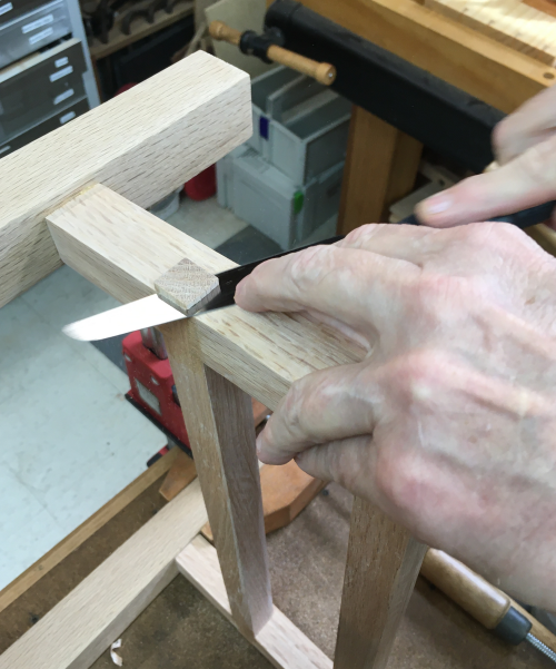
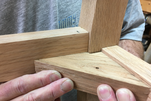
Turned to the glue blocks...definitely not clearly defined by Rodel...corner is not square and the piece must fit around the leg...had to first determine the angle...each corner will be slightly different... |
 |
After creating the angle, it was possible to notch for the leg. |
 |
Webbing Attachment to Frame
|
|
The fasteners that I used...staples and tacks...were way less than satifsfactory for this particular task. Staples: Pneumatic 18 gauge gun with crown staples (1/4 inch)...this staple is not ideal...it is just not wide enough at the crown...but that is the narrow gauge, narrow crown Porter Cable gun that I own...(model NS100B 1/4 crown, 18g). Lenth used: 1/2 inch |
|
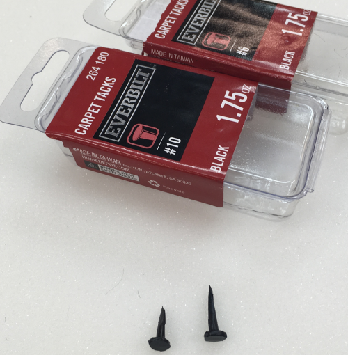
The tacks that I had available were not designed for this task, they were # 6 and #10 carpet tacks...points and taper geometry were very poor for this task...caused some splitting...but they were cheap and available at the local BORG.
|
 |
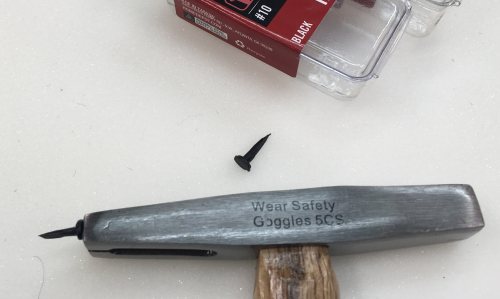
These were attached using an upholstery
hammer...the really cheap model 5 oz hammer had a striking end that
was at least bareable but the magnetic end was extremly poor. |
 |
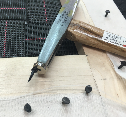
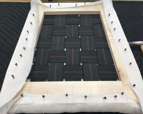
The two inch wide webbing must be stretched taut before it is attached with staples and tacks. The first step is to secure one end of the webbing...I laid it out in proper location and then put in two quick staples. |
 |
After adding 4 short #6 tacks, I trimmed out with a few more staples, then turned excess length material back onto itself and addded two longer, # 10 tacks...then finishing off with staples. |
 |
With the away end secured, I pulled the material towards me...using the tool, I stretched the material and quickly hammered in a tack...
this is a shop built spiked style webbing stretcher...see build here. |
 |
Continuing with the hammer, put in a diamond of #6 tacks into the single ply webbing. Then folded the webbing over and secured the flaps with #10 tacks (into double ply) and staples. |
 |
The webbing installed on the frame...test fit in chair. |
 |
Frame and webbing ready for next step... |
 |
The frame was traced out onto the high density foam...with a 1/4 added to all sides.
|
 |
This HD foam is 1 inch thick. I cut it at the bandsaw. |
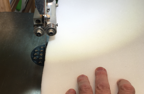 |
I used 3M 77 contact adhesive on the webbing and the HD foam. Waited 5 minutes for maximum tackiness...laid frame down onto foam carefully.
|
 |
After the webbing/HD foam sandwhich was
ready...I used a rasp to knock off all of the edges that will contact
the show material when it is pulled taut. |
 |
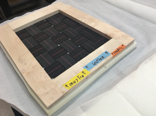
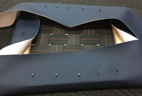
The application of the underlayer of muslin is the stage where the true shaping of the cushion is made...first I laid out the tack/staple lines of the three fabrics that will all be connected to the frame..., muslin, vinyl and cambric. |
 |
I had had problems getting tacks to be held by the lousy magnet on my tack hammer...i fixed that by attaching a rare earth magnet to the hammer.
|
 |
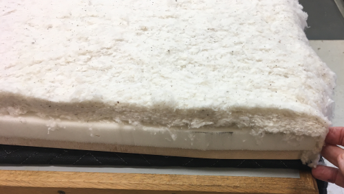
...a layer of cotton batting is added to the HD foam ...I put it flush on the sides and back and formed a waterfull over the front edge. |
 |
The muslin under layer is cut about 1.5 inches wider than needed...then it is tacked in the middle of each side...and made reasonably taut... |
 |
The smoothing process is done by pulling select tacks...smothing the muslin,..and then retacking...when finally happy the stapling is done... 3/8 crown by 3/8 legs. Tacks removed. |
 |
The muslin is worked to the corner...the front, show corners are the most important....our first corners...these are at the rear of the slip seat...there are notches that affected the corners. |
 |
Cindy was much more adept at working the corner "smile" than I was... |
 |
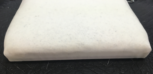
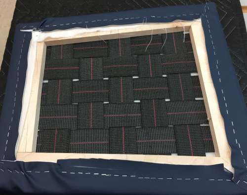
The slip seat, with the muslin under layer installed, is said to be "in the white"...this is how furniture would have been made in colonial times...sold in the white and the client would have it upholstered to their taste. Seat felt good...had a good spring...had a nice cushion layer. Ready for show cover...vinyl leather. |
 |
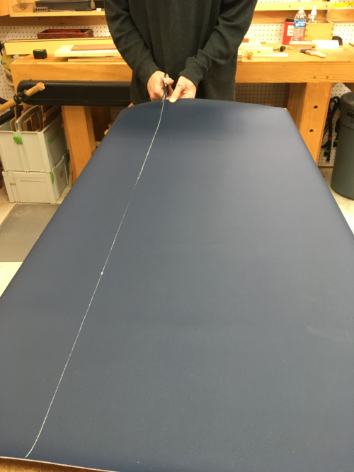
Measured out and cut vinyl leather blank... |
 |
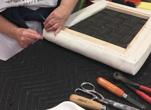
Pulled reasonably taut and hammered down tacks to hold material to the underside of the frame... |
 |
Then stapled the sides down. |
 |
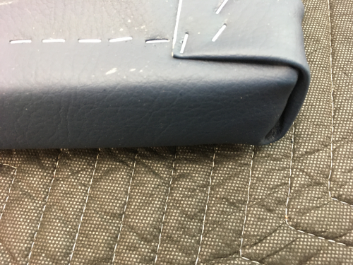
Cindy and I then stapled off all of the corners...the "smile" of the show face folds over the the inner fold of the vinyl. |
 |
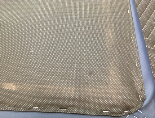
Finished the dust cover on the bottom...tacked off and then stapled. Did a poor job...did not care. |
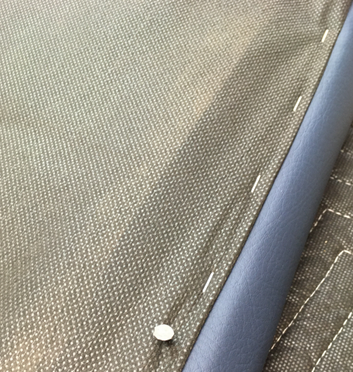 |
Its just a dust cover... |
 |
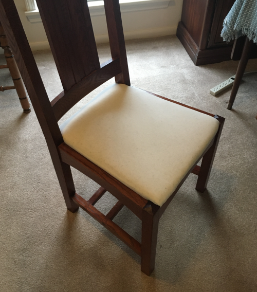
Finished slip seat in place. |
 |
Dry fit... |
 |
| Screwed the chair glue blocks to the frame | |
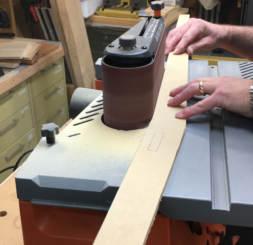
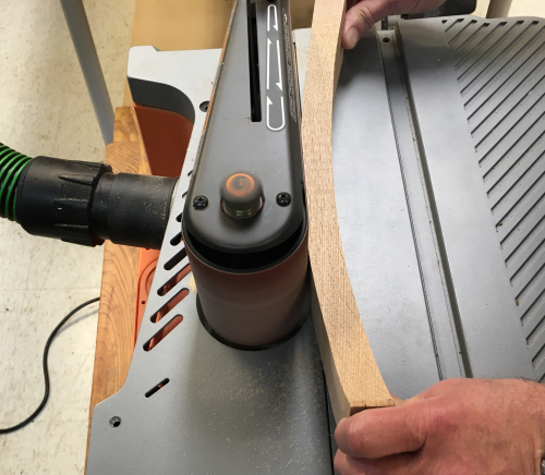
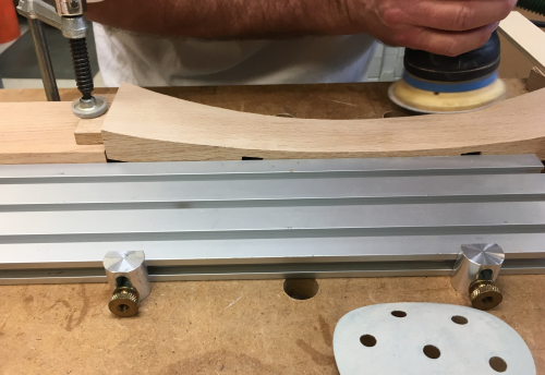
Sanding the convex and concave surfaces of the crest rail and the lower rail. First work was at the Ridgid sander with oscillating belt fixture with 80x. Some surfaces were put flat against the belt...like this rear of the lower rail. |
 |
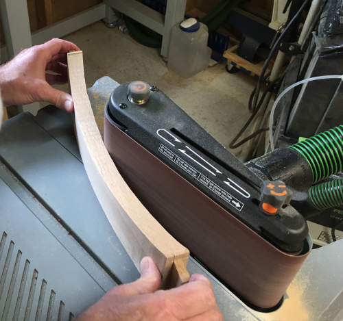
...working the concave surface was best done at the rounded end...this is the concave front of the crest rail. |
 |
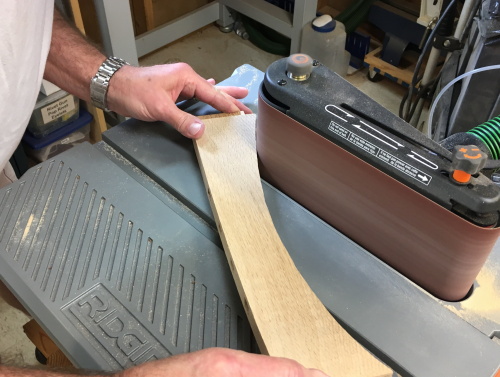
...the concave top of the crest rail. |
 |
Removing the bandsaw marks and the 80x grit...this was done with card scrapers and sanding blocks |
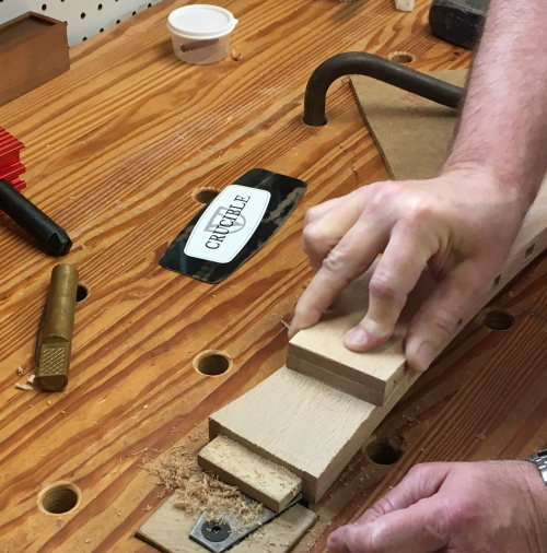 |
...blocks were made from concave and concave cutoffs with 100x sandpaper stuck to them... |
 |
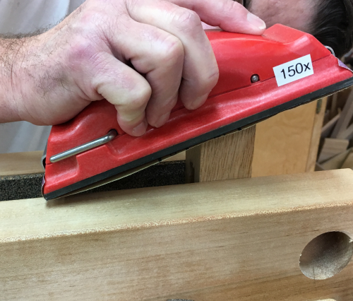
The Rotex 90 was used with grit progression of 80x, 100x, 220x to 320x. |
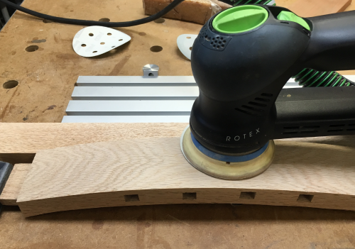 |
The shapes were difficult to hold down and steady...flexibility of the MFT3 was the ticket...and sander was very effective. |
 |
The finished parts...view of the top edges of the crest rail and the bottom rail... |
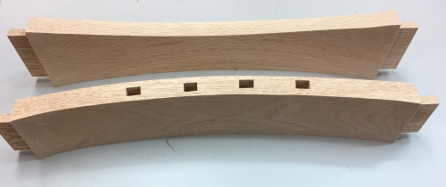 |
View of the lower edges and the concave fronts of the crest rail and the bottom rail. |
 |
The splats and rails were power sanded 90mm
at 120x...and then hand sanded at 150x-220x. |
 |
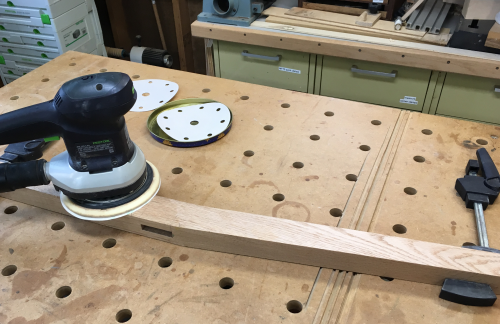
Final sanding of all parts...most surfaces were power sanded 150 mm Rotex, 120x-220x-400x |
 |
| Where appropriate...for example the chamfered pyramids...hand sanding was the option. |
 |
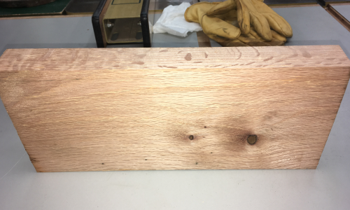
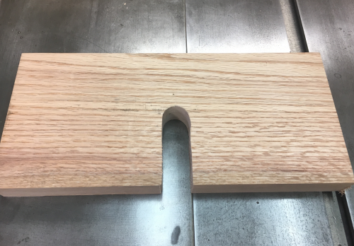
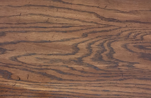
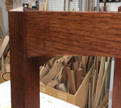
Wanted to produce a finish that would look good on an A&C period style chair...plus wanted it to reasonably match the rolltop desk. This image is one of the writing boards that comes out of the desk. |
 |
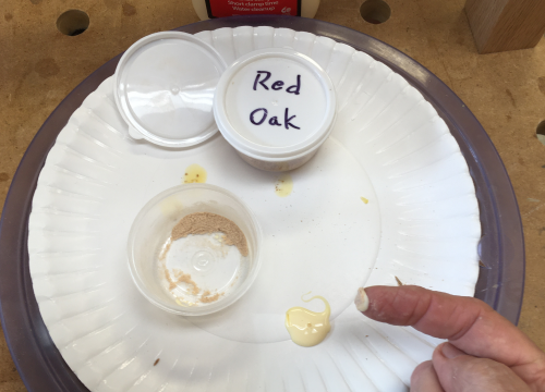
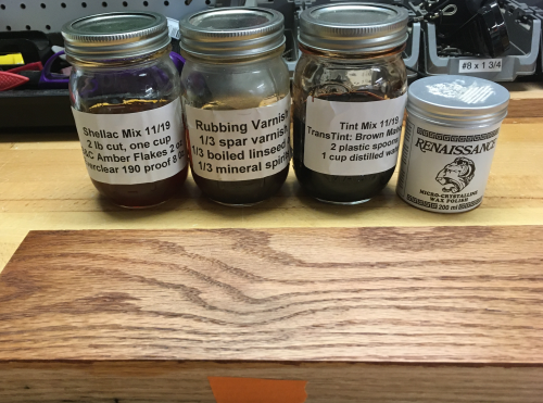
Settled on trying to tint the product...purchased TransTint concentrate.
|
 |
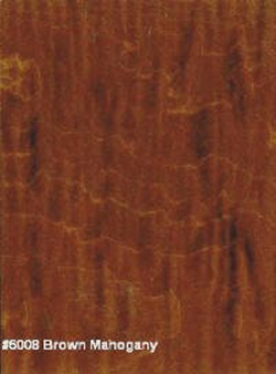
Brown mahogany color swatch online... |
 |
The tint mix...lost my notes but to the best of my memory I calculated about one tbsp to one cup of water.
|
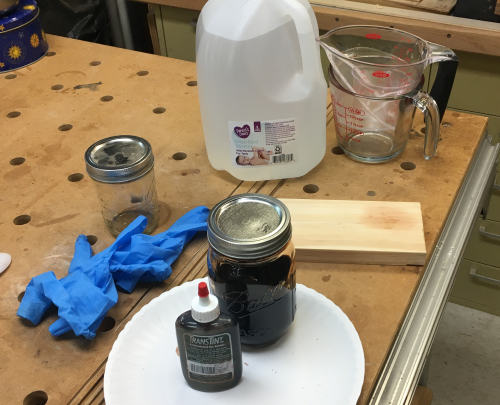 |
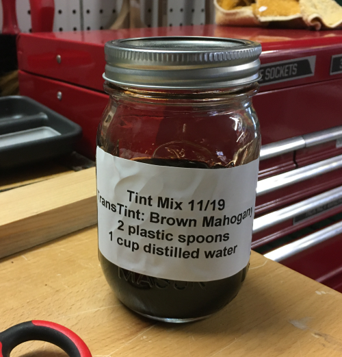
The mix was two plastic spoons (~one tbsp) of tint to one cup of distilled water. |
 |
Finish test... Test is on a red oak board in three variations...left end (blue) is tint/varnish version, center will be varnish only version, the right end (orange) will be the tint/shellac/varnish version The test chart is here. |
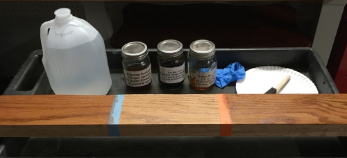 |
The winner was the orange end version...shown here with the ingredients. |
 |
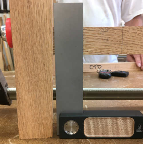
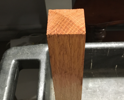
I forgot to do a test on an end grain...especially
interested in the chamfered pyramid tops of the legs...used a CTD to
check tint effect...it did not darken as much as I thought...however,
the piece was not sanded as much as the real chair part and I did not
do the water grain opening step...thus, the tint ran as opposed to being
totally absorbed. |
 |
Finishing process...began with sponge bath of distilled water...the next morning a 320x light sanding to remove nubs...then applied first coat of tint...using a foam brush...with a wipe cloth for heavy areas or foam ups. Image shows stark contrast of the tint on the oak...it absorbed more readily and went much darker on the red oak... |
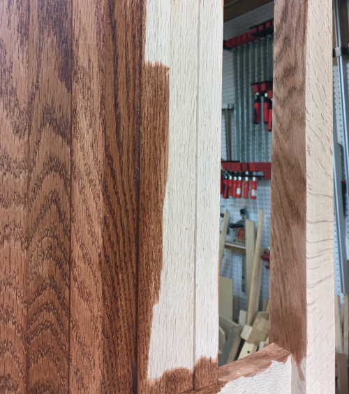 |
After one coat... |
 |
After second tint... |
 |
Two coats of brushed on amber...one coat
of varnish. |
 |
Had a major drip from the second tint layer...I thought I could work through it but it got worse as shellac and varnish were applied...so I sanded the drip out...then I was faced with a section that was just way too light.
|
 |
Tried multiple coats with little to no success...then
I mixed two drops of tint into a spoonful of amber shellac....dabbed
on coats until it got reasonable... |
 |
|
|