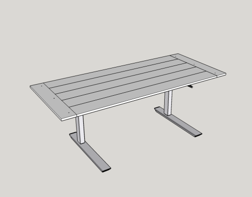
This table was made to serve as a variable height work table in the office of my son-in-law, Paul. The manual table lift kit was ordered from Lee Valley... a breadboarded slab of African mahogany was affixed to the lift kit.
|
|
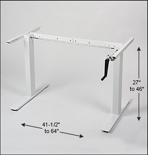
The lift kit is model #00S80.37.
|
 |
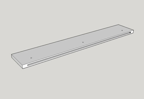
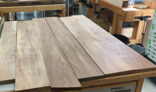
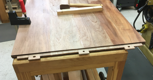
The breadboarded top will have a slab of four six inch+ wide boards...for a total of 26+ inches wide. The exposed length of the slab will be 40+ inches with a total length of ~48 inches with the two breadboard ends added. |
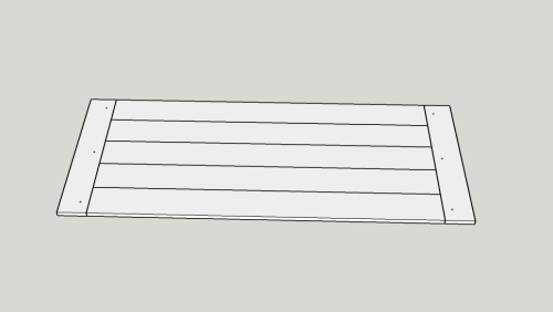 |
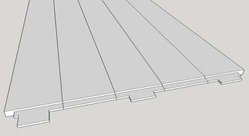
The breadboard ends will be 3 inches wide. They will have a 3/4 inch deep by 1/4 inch wide mortise ...stopped one inch from the ends. The haunch will fit into this mortise...there will also be three deeper sockets...1 1/2 inch...to accept the three tenons. |
 |
The rest of the boards will have a 3/4 inch long haunch. The two outer boards will have 1 inch sawn shoulders. |
 |
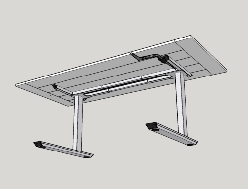
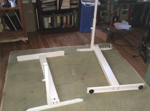
My preliminary Sketchup is utilizing a downloaded base unit that is not of the exact type that we will us...but it gives a general idea. |
 |
|
|
|
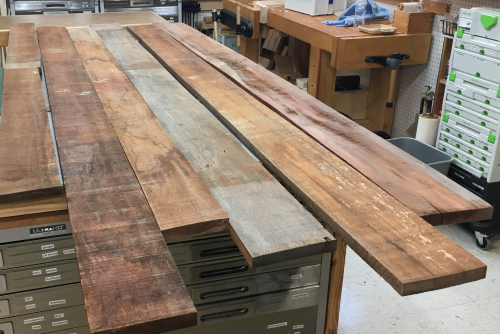
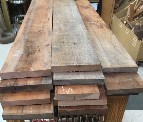
I purchased some 4/4 rough African mahogany stock from Larry at Heartwood in Star, MS. Boards were ~6 inches wide and ~8 1/2 feet long.
|
|
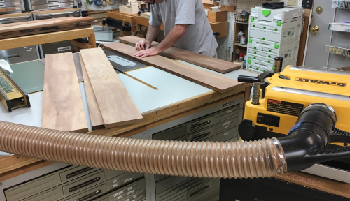
First thing I did was to calculate the cuts on all of the rough stoock and chopped the boards down to more easily worked sizes. |
 |
Cindy and I worked one surface face and squared one edge on the jointer so that I could select the blanks...these boards are all furniture manufacturer's seconds...so it is somewhat rough and varied stock. |
 |
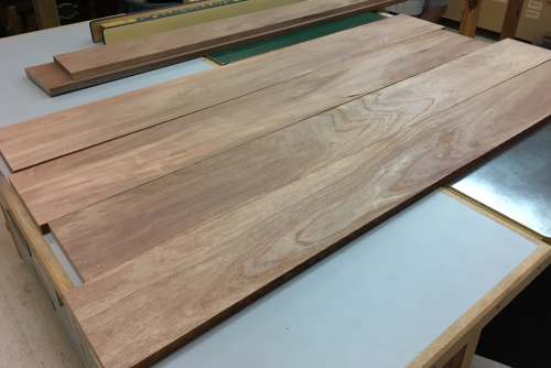
The selected blanks were planed to 3/4 inch. |
 |
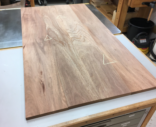
Then final placements were determined...grain run, color issues, etc. |
 |
Squared and cut to length. |
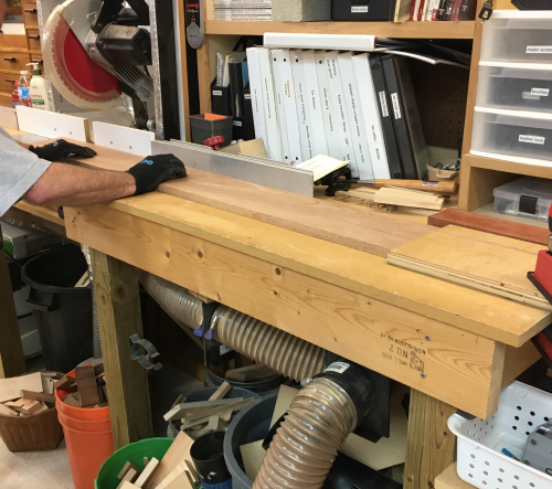 |
Final layout with marriage markings... |
 |
The many steps of the glue up were planned out... |
 |
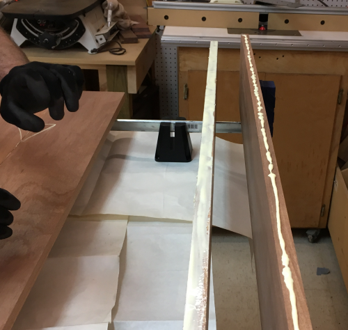
Edges received glue.. |
 |
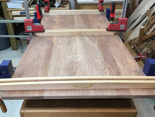
Many clamps and cauls... |
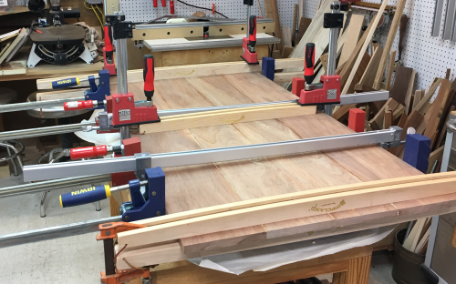 |
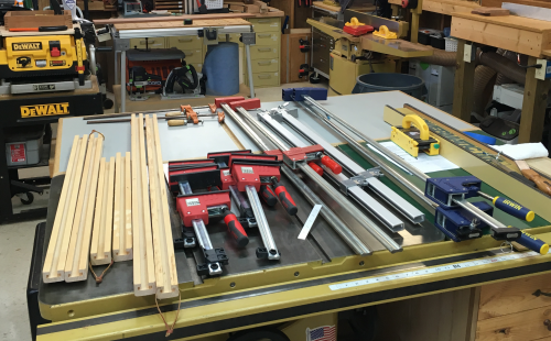
Out of the clamps...lineup of many devices ...6 bow cauls, six Besseys, 2 Dubuques, two Irwin and two F type... |
 |
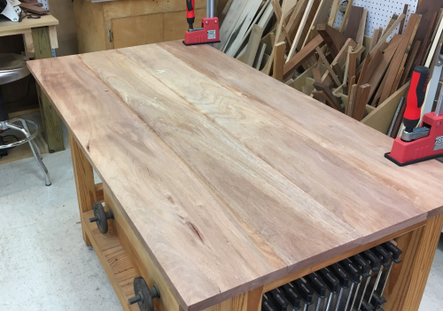
Preliminary cleanup done... |
 |
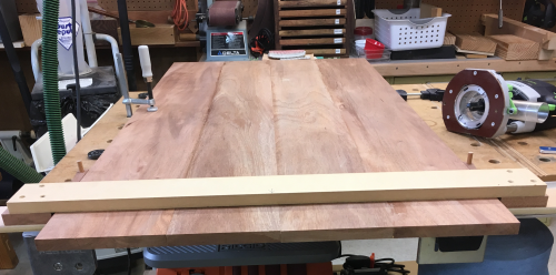
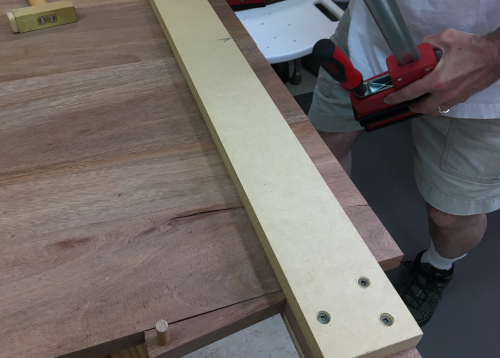
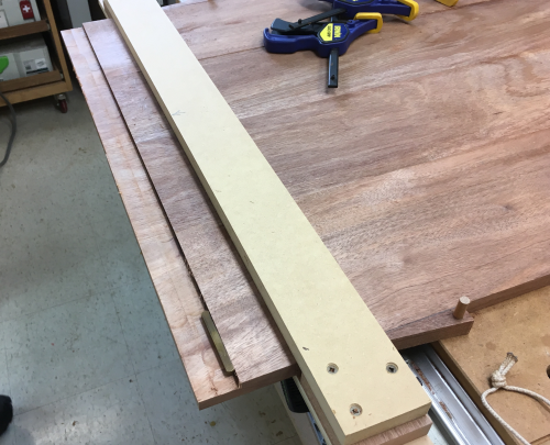
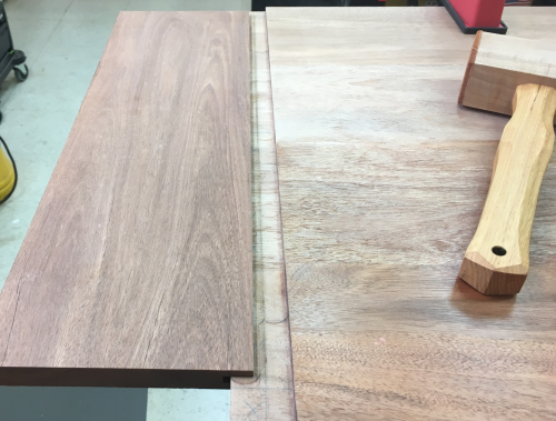
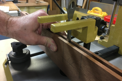
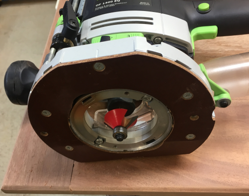
Ready to put the tenons on the end...made a jig that will become a fence to allow the tenons to be cut with a router...it fits over the workpiece and allows the fence to be set on both the top surface and the bottom surface. |
 |
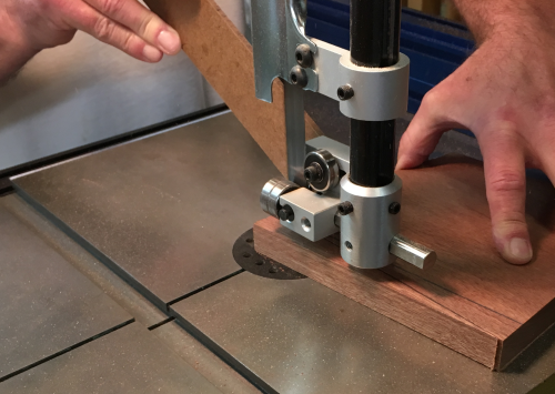
...at the bandsaw, cut out some wedges that will be used to lock the fence in place... |
 |
...a wedge in place. |
 |
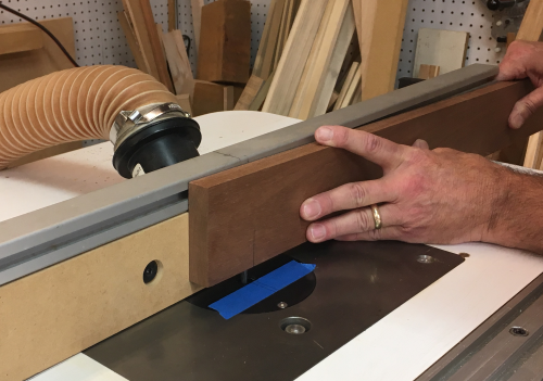
Using a spacer piece, first flat and then on edge, enabled two router runs to make about 1 inch of the tenon...the final run, against the jig fence, provided the tenon shoulder. |
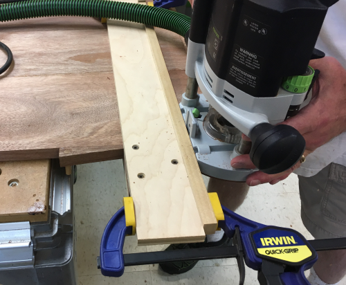 |
The African mahogany was not gentle on router bits...the 3/4 router struggled and overheated...I later destroyed it... The tenon...one side done...measured to make the 1/4 inch tenon fat...then flip the tabletop and do the same routing on the bottom side. |
 |
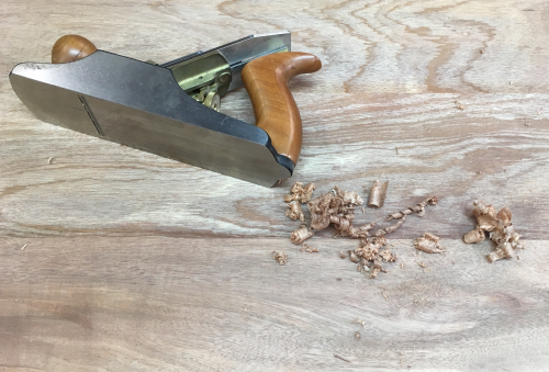
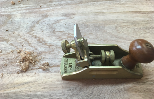
Tenons were worked to a happy state with the LV skew rabbet plane and sanding... |
 |
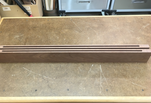
Mortises were made with 1/4 inch router bits...CTD with through grooves was used to get spacing right. |
 |
Since these are stopped grooves, the breadboard ends had to be dropped down onto the bit and picked up at the appropriate location |
 |
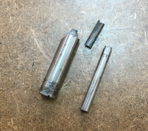
The African mahogany was tough and wonky and we broke off both two-flute bits we tried...one was a 1/4 shaft, the other a 1/2 inch shaft... I picked up a new, carbide up-cut spiral...we lessened the increments of raising the bit to 1/8 inch per pass...this drastically reduced the stress as to cutting depth. Bit quality was a step up also. |
 |
Stopped mortises 1/4 x 3/4 inch deep... |
 |
...we then laid out the deep mortise locations... |
 |
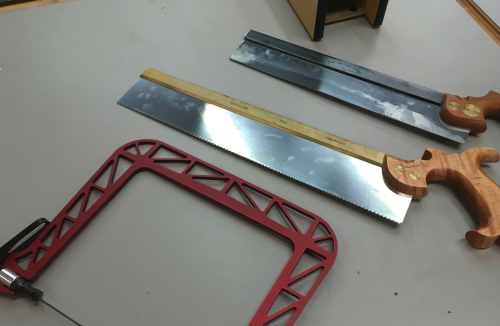
For cutting the tenons...cope, LN xcut, and Bad Axe rip... |
 |
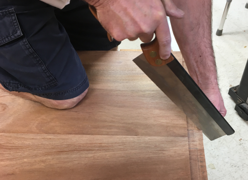
Ripped, cross cut, and coped with the table slab on saw benches... |
 |
A finished tenon...copes in the wonky wood gave ugly edges...they will disappear forever in the mortise... |
 |
Laying out for the location of the deeper mortise pockets. |
 |
The deep pockets will be 1 1/2 inches...the mortise chisel was lined up to work straight into the existing groove and then plunge further to the final depth. |
 |
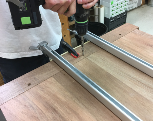
Holes for the 3/8 inch dowels were drilled...about 3/4 inch out from the shoulder. About time to remove the piece for final prep... |
 |
The holes on the outside tenons were elongated with rat tail rasp...toward the outside a little bit and something more toward the inside... |
 |
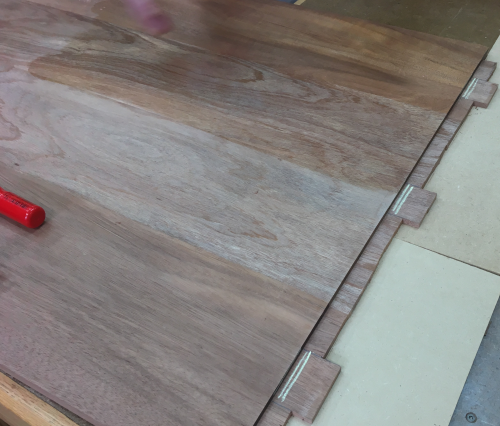
Finished end unit...ready to be pegged. |
 |
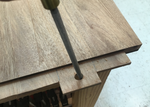
Oak dowels were put in place...the center dowel was glued all the way...the outer pegs only got glue on the top 1/3...(see left dowel in image)... |
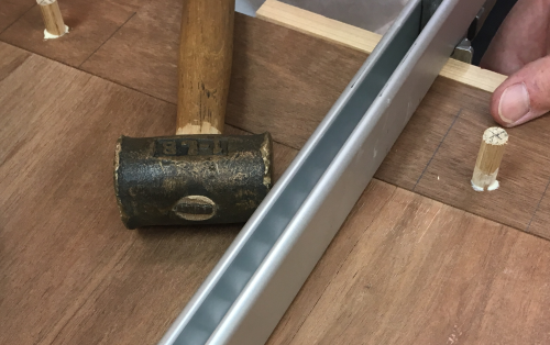 |
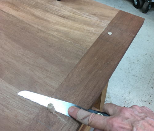
Dowels flush cut... |
 |
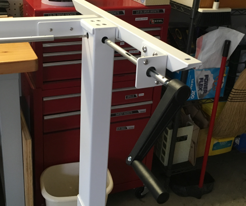
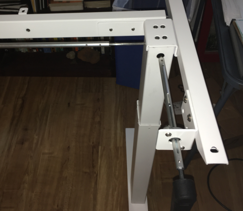
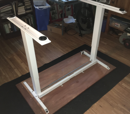
Regarding the "Made in China" lift kit...I was very pleased that the metal supports were reasonably stout...but the hardware and milling were barely acceptable and of course, the instructions were truly horrid. |
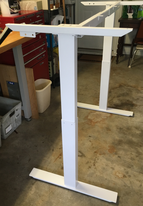 |
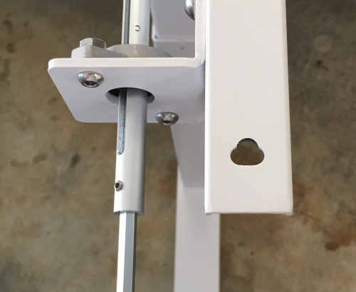
There were no instructions at all when it came to putting together the most difficult sub-assembly. The instructions basically said "Install the handle"...not mentioning the dozen important insertions, adjustments, and tweaks that were required to make the right leg lift assembly work... |
 |
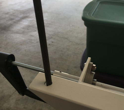
...and then the lift function from the right leg had to be mirrored in the left leg... |
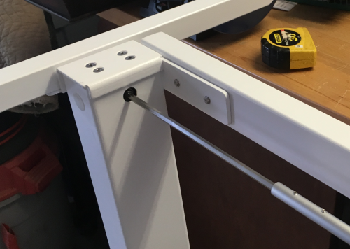 |
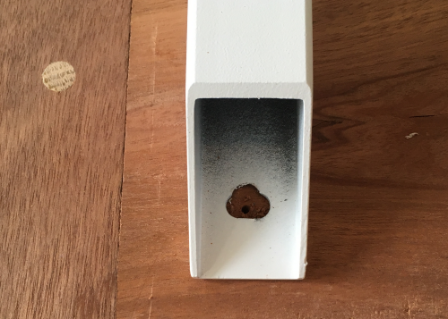
The predrilled holes in the base did not line up in a way that would be acceptable for wood movement...so the four leg hole locations were elongated in towards the centerline...used a couple of rat tail files... |
 |
...an elongated hole... |
 |
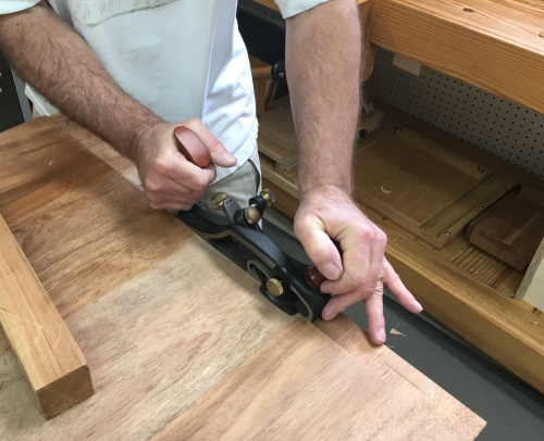
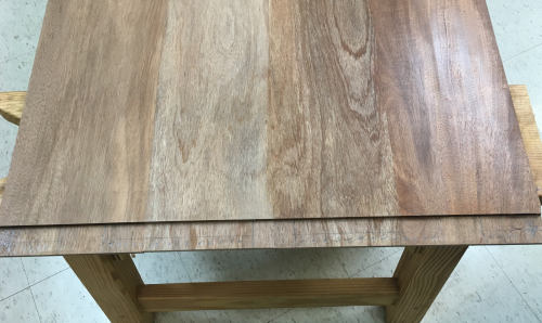
Surface prep was difficult...the wood was very active and figured...lots of directional changes...used the 55° high angle frog on the LN #4 smoother... |
 |
...then LN 212 small scraper plane...then cards... |
 |
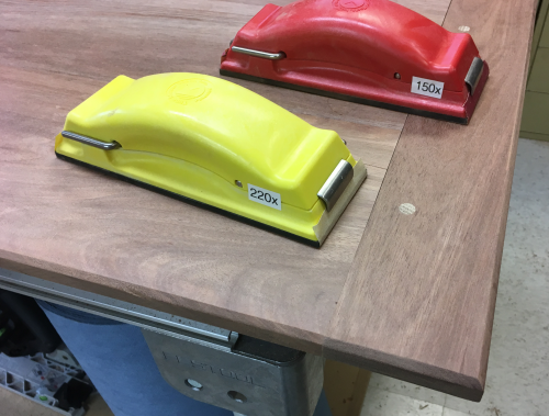
The breadboard ends were deliberately a little fat and they would need to be leveled out...started with 60x on Rotex 150mm. |
 |
Progressed 60x, 80x,100x, 220x, to 400x... |
 |
The outer edges, on the top and bottom, were chamfered... |
 |
And then hand sanded 150x to 220x... |
 |
A rubbed on coat of amber 2 lb. shellac...the top ended up getting two coats... |
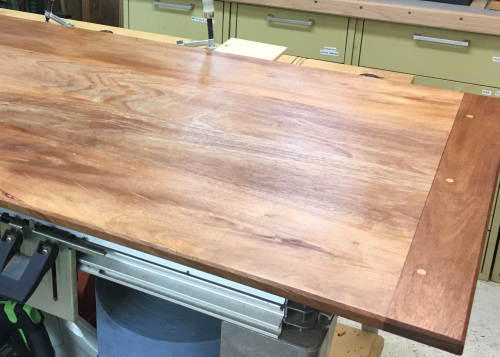 |
The base unit had been assembled in the garage, so James and I took the completed top there and did a final dry fit and base adjustment. |
 |
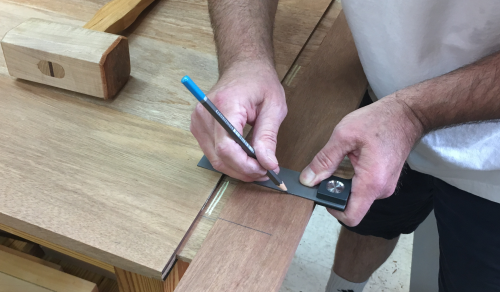
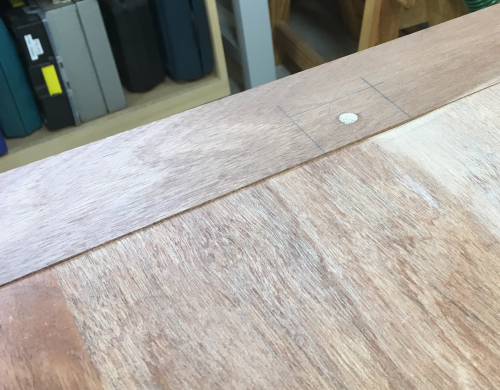
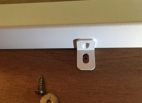
The top was put face down on a blanket and the screw holes were laid out. |
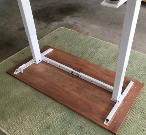 |
The screw hole was placed in the center of the round holes...as the top shrinks there will be room to move towards the centerline. |
 |
After full assembly, the unit was disassembled...Cindy and I then transported all the parts and tools to Paul's office...the parts were laid on a blanket... |
 |
...the base and drive mechanisms were reassembled. |
 |
The screw holes were lined back up...final adjustments made...#8 x 3/4 inch square drive screws were used with small hole fender washers. |
 |
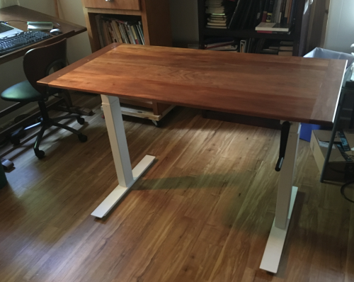
The top was screwed back on. |
 |
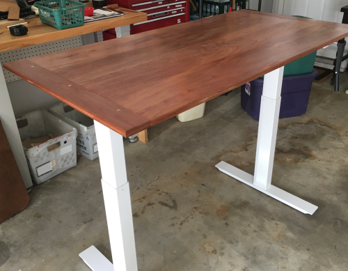
The finished product. |
 |