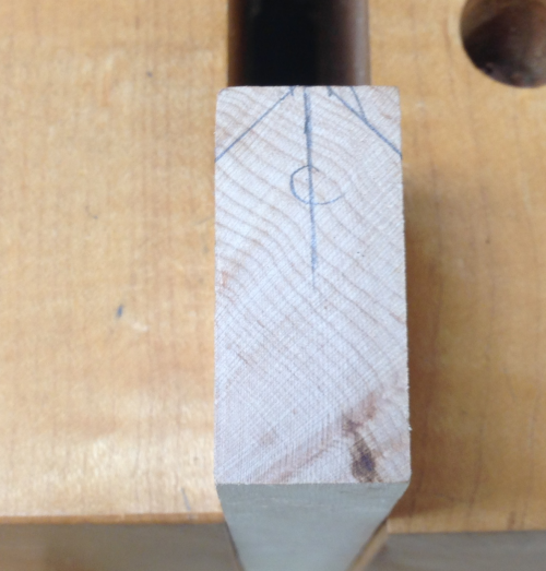
A current project (a cherry step stool) needs mortises cut at 10 degrees. I decided to build a jig to improve my ability to drill on an angle at the press. My first thought was to create a jig fixed at 10 degrees but then opted for a variable jig.
|
|
I searched the web for some ideas. I liked the look of this one... The materials will all be wood or jig parts left around the shop.
|
 |
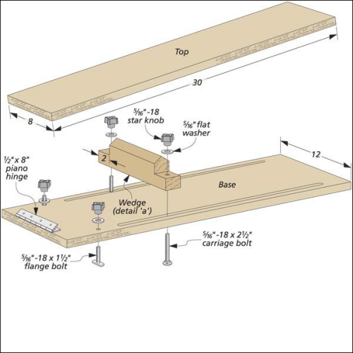
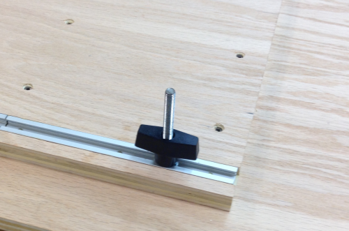
There is a wedge that is movable and lockable that changes the angle of the hinged top plate. |
 |
| Side view of the wedge assembly... |
 |
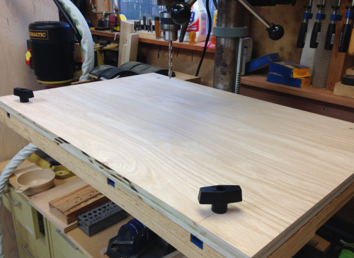
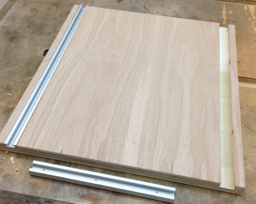
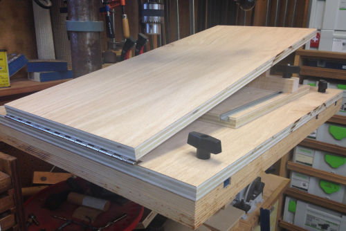
I made the base plate (3/4 inch red oak cabinet grade plywood) 28 1/4 inches long. This matches the width of my drill press table. The 18 inch width of the base plate allows the front edge to be co-planar with the front edge of the table with a small amount of room at the back. |
 |
Cindy and I drilled 5/16 inch holes that allowed for a 5/16 inch 18 thread t-bolt to fit through and slide into the existing universl t-track slots. The hole locations were centered on the t-track slots... |
 |
...and then laid out on the base plate. |
 |
The base plate secured to the drill press table. |
 |
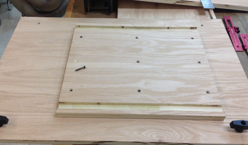
Rather than have the locking t-bolts for the wedge come through the base plate, I created a plywood wedge plate that has t-bolt tracks. The plywood was 14 inches by x inches. I routed a 3/4" wide by 3/8' deep dado at the router table. |
 |
The two grooves were 1/2 inch off the edges and will accomodate the t-bolt tracks shown. |
 |
The wedge plate was installed into countersunk holes with square drive #8 x 1.25 inch screws. The plate is four inches off the far, right end of the base...and x inches off the hinge end (the left end in this image). |
 |
The wedge plate was sawn to be just long enough to accept two tracks that I recycled from an old jig. They will be installed butt end to butt end. The longer piece of track was cut to fit. |
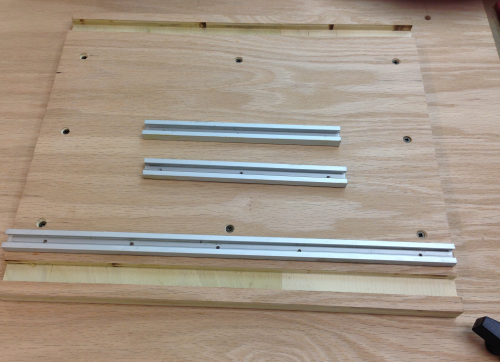 |
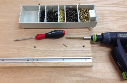
Square drive #4 brass screws were used to screw down the tracks. The screws used were 3/4 inch long so they secured the track and went 3/8 inch into the lower plate. |
 |
The t-bolts used with the wedge will be longer to extend through a couple of inches of the wedge board. |
 |
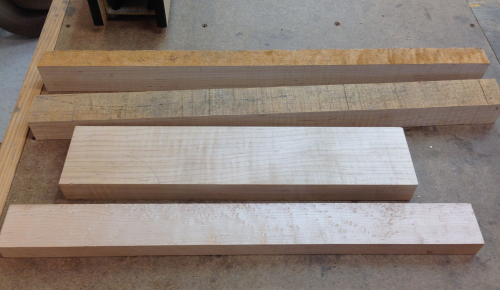
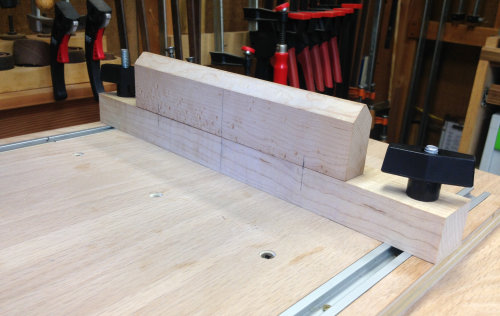
I had no idea how tall to make the wedge. I decided that I would use some maple that was lying around and make it the height of the materials on hand. The wider boards shown would become wedges and the two rough boards would become bases. After trying out the jig I could always create a taller wedge. |
 |
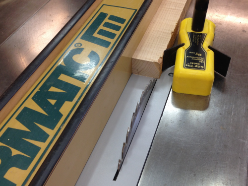
The base blanks had previously been surfaced on a face at the jointer and then on edge to create a squared edge. So I planed the opposite surface and then ripped the edge on the table saw. |
 |
I did not want the edge of the wedge to be so sharp that it had no strength...so I opted for two 45 degree cuts that would leave a central flat portion. |
 |
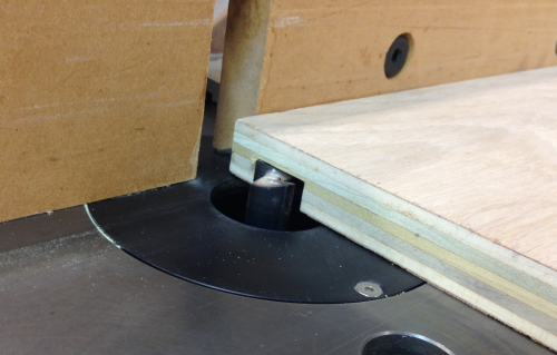
The 45 degree was put on with a chamfer bit at the router table. |
 |
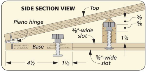
I kept sneaking up on the egde until I like the look of it. The height of this wedge is 1 7/8 inches. |
 |
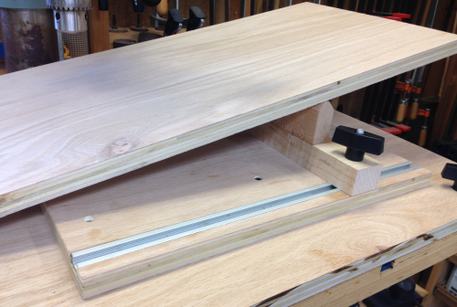
A dry fit to see how everything looked...the height of the support base is 1 3/16. After adding in the 3/4 wedge plate thickness, the total relative height of the wedge in relationship to the base plate at the hinge end is 3 13/16 inches. |
 |
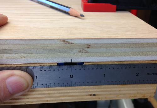
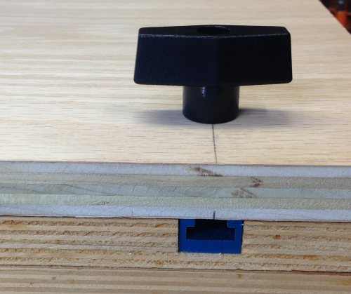
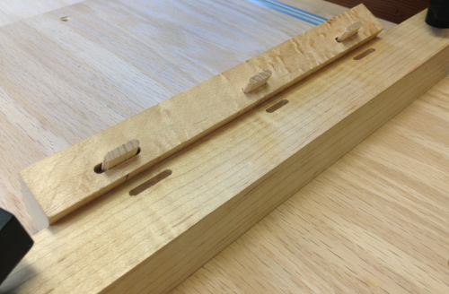
To join the wedgne to the support base, I used the Festool Domino device and my jig to create floating mortises and tenons. |
 |
The wedge support base had 5/16 inch holes drilled for the t-bolts and the support base was then secured using t-bolts and knobs. The Domino pattern was tight in the center and loose on the ends for easy attachment. |
 |
This is a friction fit that will suffice until I know if the height is appropriate. It is conceivable that I will make taller wedges and just friction fit them onto the wedge support base. |
 |
Test fit to see how the angle turns out...the placement of the wedge had been totally arbitrary...the dry run was ~11 degrees. |
 |
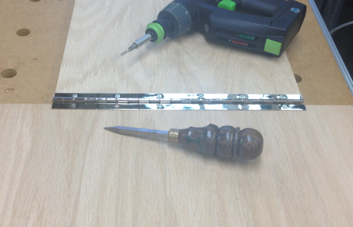
Attached the top plate to the base plate with a 12 inch piano hinge. |
 |
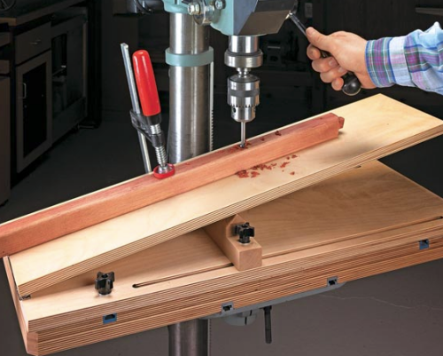
Tested out the device. The angle was 10.25 degrees. |
 |
|
|