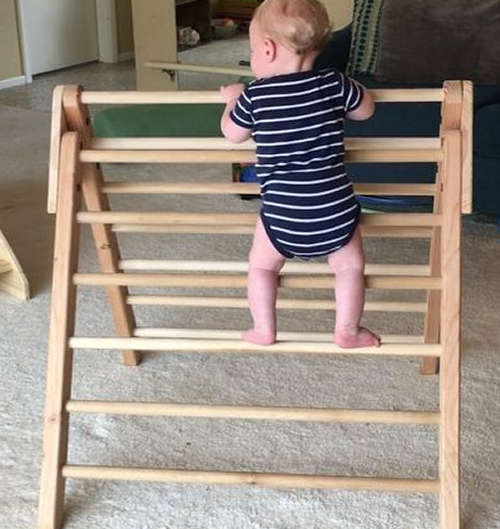
Pikler Triangle Emmi Pikler was a Hungarian Pediatrician who developed a theory of child development theory in the 1930s/40s. The concept was based on providing opportunities for the child to move freely and develop at their own pace. Parents and caregivers don't put the child into any position they can't get into by themselves. It also means that caregivers should provide ample opportunity for the child to put themselves in positions to encourage self development. It also means giving kids the opportunity to learn how their bodies can move (and climb) – hence the Pikler Triangle.
Assembly: Slant Board
|
|
A Pikler Triangle for climbing...used this image somewhat as a prototype.
|
 |
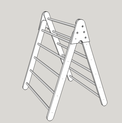
The unit must be safe, sturdy, portable, foldable, and easy to setup |
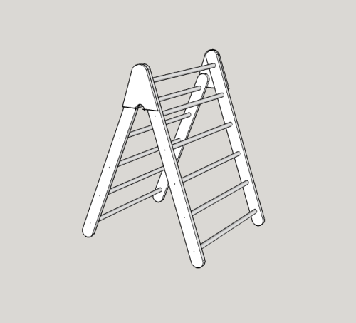
My terminology... long rack= one side consisting of 2 long legs, plus 6 rods short rack = one side consisting of 2 short legs, plus 5 rods two pivot plates connect the racks |
First Sketchup model... rough dimensions when setup for use... width = 36 3/4 inches depth = 33 1/2 inches height = 44 5/8 inches |
 |
The two triangular pivot plates will be made of 3/4 inch red oak pywood, hope to find some quality EuroPly online. |
 |
The long rack will have two stile boards that will be milled from red oak planks. They will be 1" thick by 3" wide by 48 "long. Six 1 " dowel rods will be ~36" long, they will insert 5/8 inches deep into 1 inch drilled holes (every 8 inches).
|
 |
The short rack will have two stile boards that will milled from red oak planks. They will be 1" thick by 3" wide by 42" long. Five 1 " dowel rods will be 36" long, they will insert 5/8 inches deep into 1 inch drilled holes (every 8 inches). |
 |
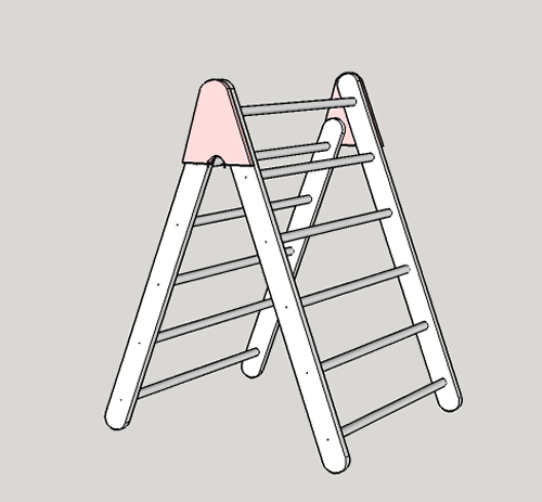
Second Sketchup..with some details fleshed out regarding the pivot plates...short legs extended two inches... |
 |
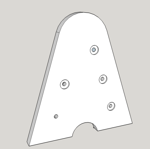
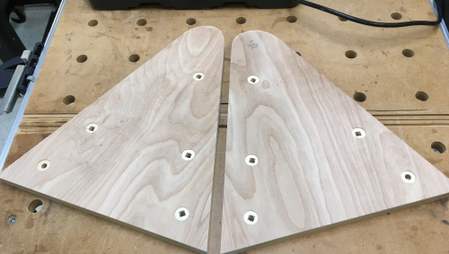
A pivot plate...3/4 inch plywood...four 3/4 inch x 1/8 inch deep countersinks for carriage bolts with through 5/16 holes...the three go into a long leg...the singleton is for the pivot bolt in the short leg. The single 5/16 hole will accomodate the knob that secures the leg but removal allows the leg to pivot and then the entire unit is able to fold for storage. |
 |
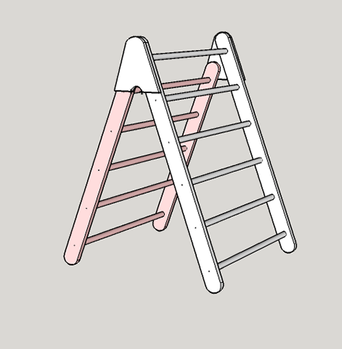
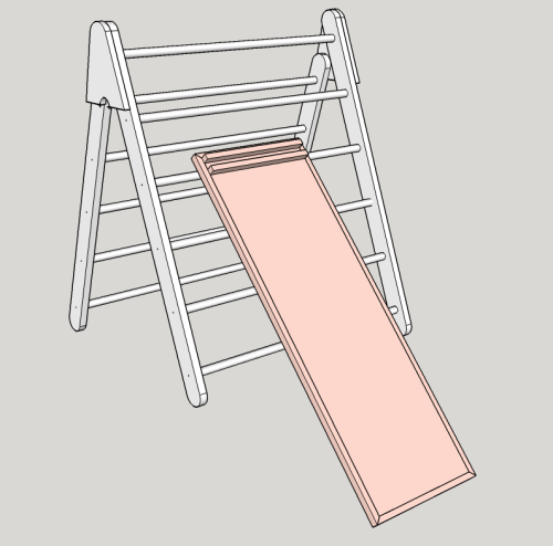
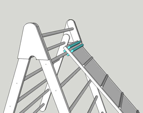
There will be a slant board...it will be 3/4 inch red oak plywood, cut to 15.5" wide and 47.75" long. It will be banded on the ends and sides with a 3/4 inch thick, one inch long piece of red oak. The banding will be flush with one side...this being the slant-slide board side...(tinted pink in image)
|
 |
The banding will stick up proud 1/4 inch on the slant-climb side...shown here tinted green. This forms a light lip at the edges of the board. The climbing strips are beveled slats that are 3/4" x 3/4 inch, chamfered edges...red oak... There are five climbing strips plus the locking boards at the top. |
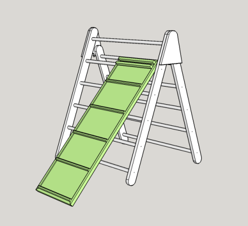 |
The lock boards are red oak, 3/4 inch by one inch. They are spread to fit onto a one inch thick rod dowel. The are chamfered for safety. There are a pair of these lock boards on both sides...shown here tinted blue.
|
 |
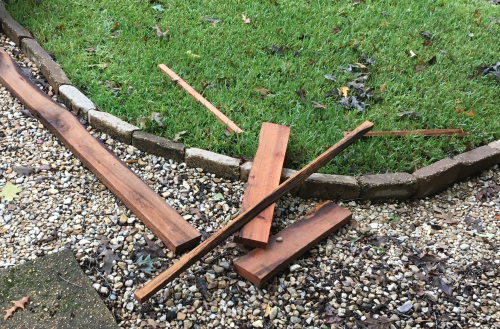
My brother-in-law, Rusty, delivered up some red oak to me. This wood was milled on a farm in south MS and stored in a barn many years ago. The wood is barn dry. Boards were about 12 feet plus, 5 inch plus wide and 6/4 thick. At the Benchmark table, Cindy and I cut them into 6 foot plus working blanks... |
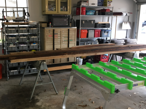 |
...and stored them to surface dry, it had
rained the day they were delivered... |
 |
...then transported them into the shop. Stored in the shop attic. |
 |
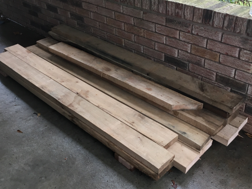
I was down to the last boards in my oak hoard...had to trash some pieces... |
 |
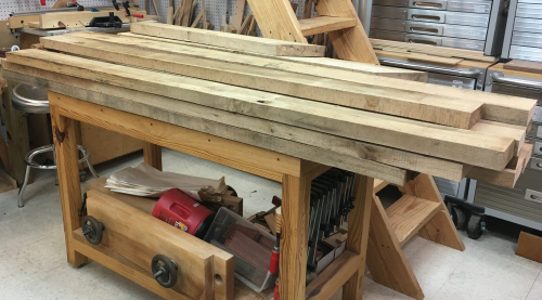
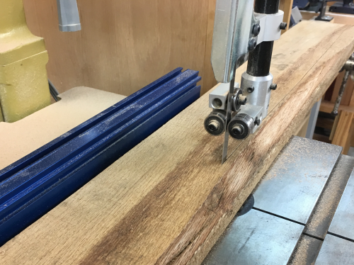
Took off irregularities at bandsaw before milling... |
 |
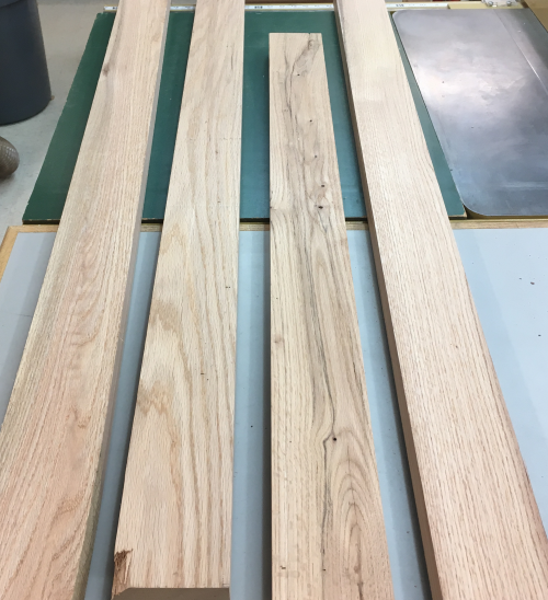
The coloration of some pieces was not very consistent... example of boards after milling...jointed a face, jointed a square edge, planed to thickness and ripped a second edge...all of these boards are milled fat in thickness, width, and length to allow for further milling after boards de-wonk a bit. |
 |
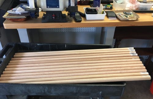
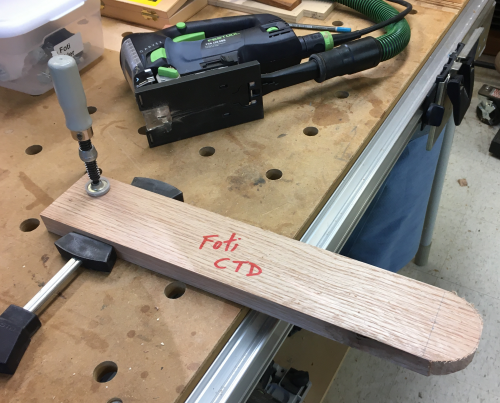
Need eleven dowel rods...1 inch oak dowels x 36 inches long... |
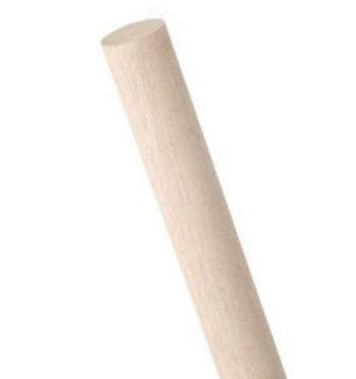 |
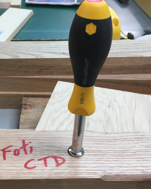
pricey but available at orange BORG...got 12 to have a CTD. |
 |
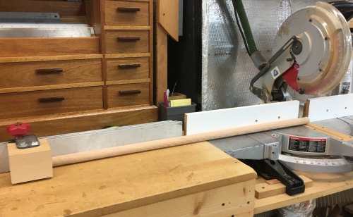
At the BORG I selected rods that rolled straight...they were somewhat irregular and certainly were not all the same length...I set up a stop at the chop saw and took off all of the ends...removing the painted ends...and guarantying a square end and a consistent length. |
 |
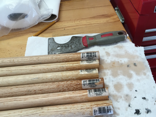
The most difficult task regarding the dowel rods was getting the labels off...they would not peel at all...soaked the labels in GooBeGone... |
 |
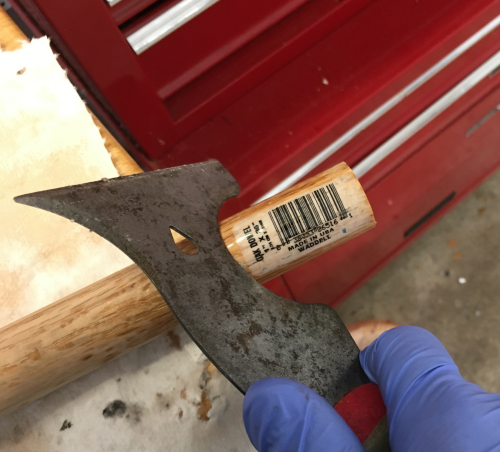
...and scraped off with the round edge of the 2001 tool. |
 |
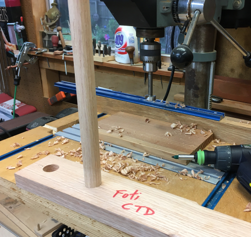
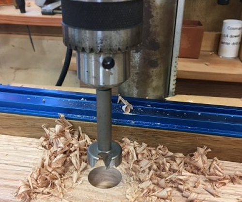
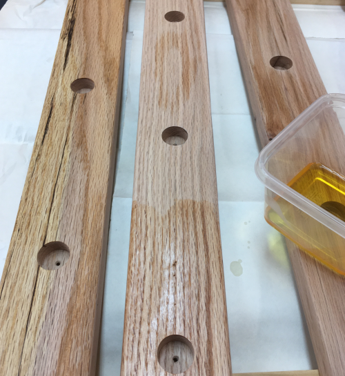
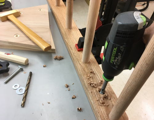
Each dowel rod will slip into a 5/8" deep, one inch hole...centered in leg, one every eight inches...this hole will be drilled on the press with a one inch FAMAG Forstner bit. The oak dowels have to be lightly sanded to fit. |
 |
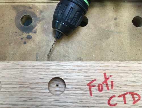
After the large hole is drilled...a smaller twist bit (5/32) is used to drill a through hole in the center of the large hole.
|
 |
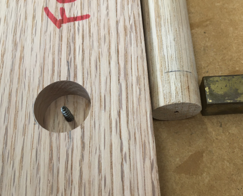
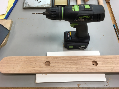
Then a #6 x 1 inch square drive screw is countersunk from the reverse side...the drilling occurs after the rod dowel is in the hole...thus it centers the hole in the end of the dowel. After the screws passes through the 3/8 inch thickness it will penetrate 5/8 inches into the dowel rod. |
 |
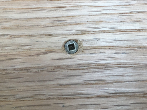
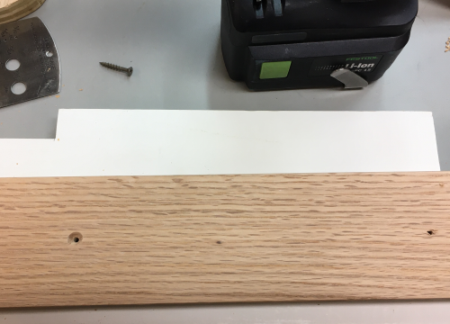
From the outer face side, the #6 screw is countersunk and will present no safety issues. |
 |
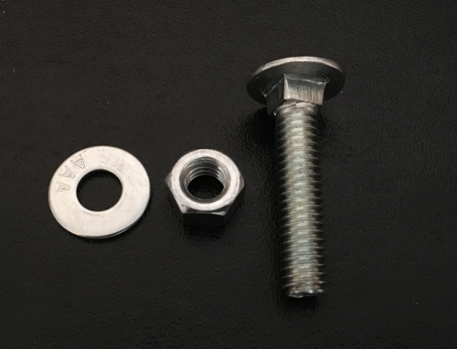
Carriage Bolts
The pivot plates will be attached with 4 each 5/16-18 carriage bolts (3 will secure the long legs and 1 will be the pivot bolt on the short leg)...length will need to be ~1 1/2 inch. |
 |
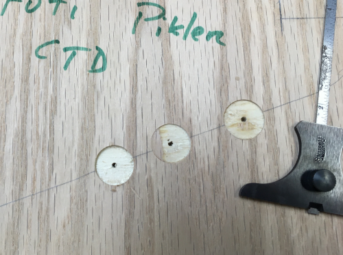
The carriage bolt head will be slightly countersunk (~1/32 ") with 3/4 ZOBO Forstner. This barely takes off the outer ply. The center pointer clearly marks the wood. Then a 3/32 inch twist bit is used to punch the center hole through onto the leg. |
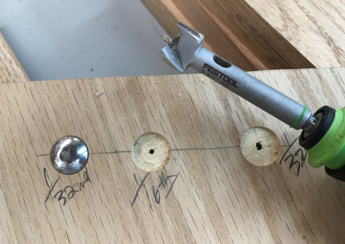 |
The 1/32 depth just allows the edge of the carriage bolt to be beneath the surface when pounded in... |
 |
The center point is then continued through just the leg to mark the center on the backside of the leg...this point locates the center of a 3/4 inch ZOBO...this hole is drilled to a depth of 1/2 inch.
|
 |
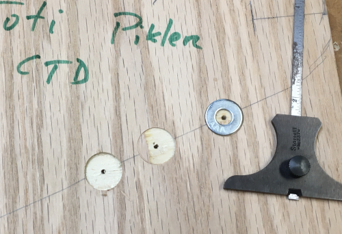
Then a 5/16 hole is hole is drilled through at the center mark... |
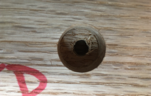 |
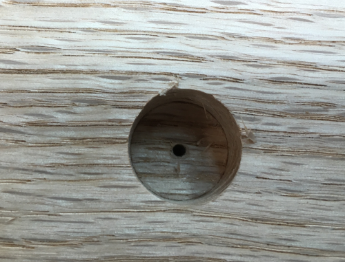
...on the backside of the legs... a washer and a nut must be countersunk below the surface for safety...(3/4 inch hole x 1/2 inch deep) |
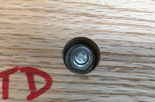 |
The thin wall of a 1/2 inch nut driver is a perfect fit to tighten the nut on the backside. |
 |
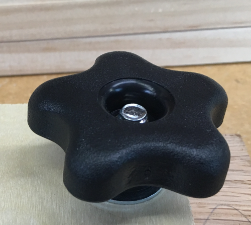
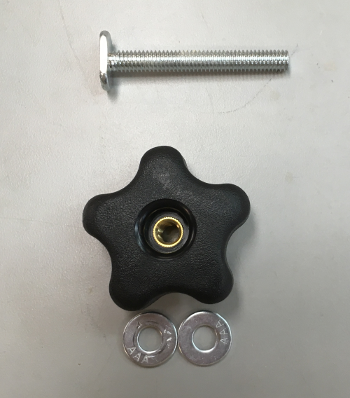
5 Star Handle & T-bolt This is the handle that allows the unit to fold.. |
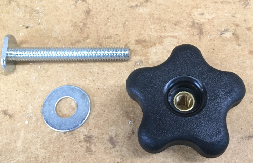 |
The star handle with a washer will be used to tighten the pivot plate. On the face of the plate a 3/4 inch hole will be barely scored (~1/32") with a ZOBO bit. Then a 3/32 hole is centered there and drilled through the 3/4 ply and into the leg.
|
 |
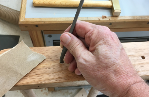
Desired depth...the washer should be slightly proud of the surface of the plate...the handle should make contact only with washer. A through hole (3/32) marks the center on the leg. Then the 3/32 hole is extended through the leg showing the location of the T-bolt...a slot for the T is laid out marked |
 |
...the slot holds the T end of the bolt in place. |
 |
For safety the T-bolt must not extend beyond the handle. |
 |
Laid out the legs...this was on the interior faces that will recieve the 1 inch x 5/8 inch deep hole... |
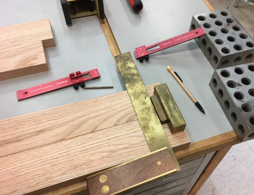 |
All four legs were laid out at the same time.. |
 |
...also laid out the rounded leg ends... |
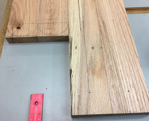 |
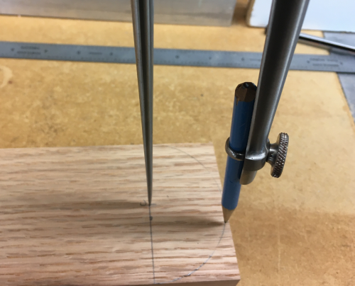
The ends of each leg was laid
out with a 1.5 inch radius...marked out with a compass... |
 |
...cut fat with a jigsaw...
|
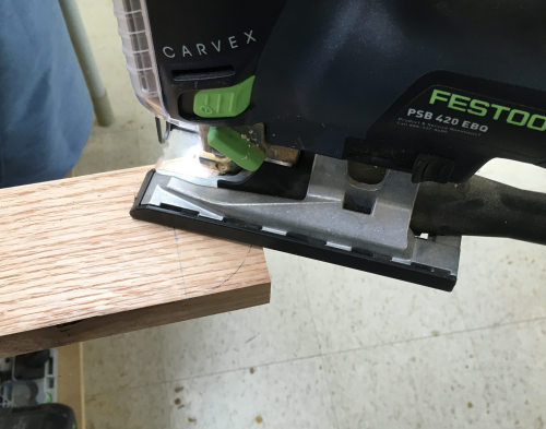 |
...stayed outside of the line... |
 |
and then finish sanded to the line at the oscillating sander. |
 |
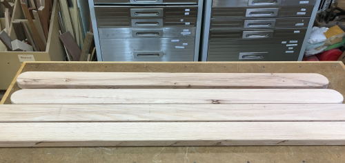
Leg blanks ready for milling
rod holes... |
 |
Each dowel rod will slip into a 5/8" deep, one inch hole...centered in leg, one every eight inches...this hole will be drilled on the press with a one inch FAMAG Forstner bit. The oak dowels have to be lightly sanded to fit. |
|
Hole drilled to 5/8 inch... |
 |
Then a 5/32 twist bit made a through center drill from the center dimple in the bottom of the hole. |
 |
On the show side, the center hole is then bevelled to become a suitable countersink for a #6 screw...countersink shoud be too deep rather than too shallow. |
 |
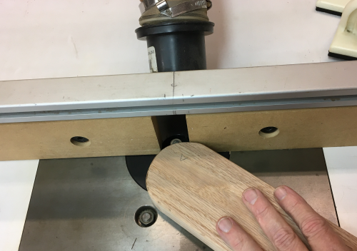
All of the leg blanks had the edges knocked off with a round-over bit at the router table. |
 |
I applied two coats of shellac to the inner leg faces because it was much easier without the dowels in the way.
Each dowel was then rough sanded by hand on each end (100x) and then fit into the hole and the countersink was run back in to put a hole in the end of the dowel. |
 |
After all the dowels was seated, the countersink bit was run anew into the show face, with the through bit drilling the center hole into the end of the dowell to accept the #6 screw shaft.
|
 |
Then the ends of the dowels were installed into a leg, screwed and glued... |
 |
All of the unattached ends were
sanded and tested in the appropriate holes... |
 |
Then the frame was set down onto sawbenches...this made for a reasonable working height of the unattached dowels... |
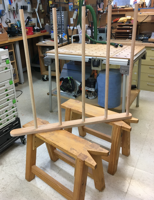 |
Dry fit: the leg was fit carefully over the dowels...tamped down by hand till all were postioned correctly...and then "persuaded" with a beating block and the lump hammer... |
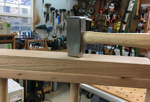 |
...after all the dowels were seated, the countersink bit was run anew into the show face, with the through bit drilling the center hole into the end of the dowell to accept the #6 screw shaft. At this point, it is still a dry connection. |
|
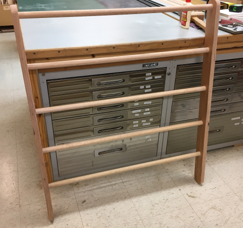
| Dowels were pulled and the holes were then glued up...the wet fit happened just like the dry fit above...then each dowel received the final screw. The short frame assembled. |
 |
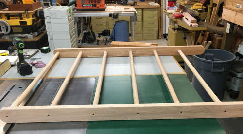
The long frame was a repeat of the above...here it is assembled. After completing the small frame, I reassessed all methods...the one that caused me the most grief was the sanding of the ends of the 1 inch rod dowels...the work had been done by hand and my thumbs and wrists suffered... |
 |
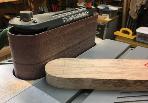
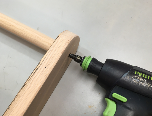
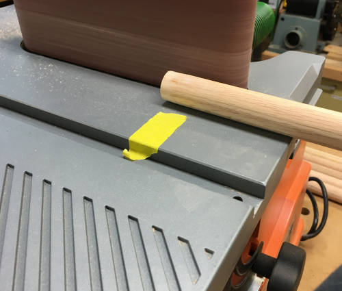
So, on the second frame I decided to take off the edges at the end without using so much hand sanding...I used the Rigid oscillating sander...the tape gave me visible reference of mater to be removed...only issue was an early error...too much pressure put a facet on the dowel (way too quickley!) ...went to a much lighter touch with a slow but steady roll of the dowel. Touched up with hand sanding. Still pretty stressful to wrists...need to find a better way. |
 |
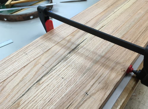
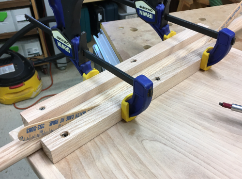
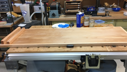
In the attic I found a piece of a grade A 3/4 inch oak plywood. Ripped it to 47 3/4 by 15 1/2 inches... I banded this ply with 3/4 inch by one inch red oak. Strips were glued and nailed off 18g x 1 3/4". |
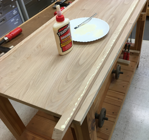 |
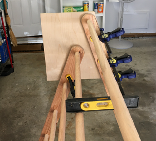
Clamped up...on the slide surface
of the ramp the banding is coplanar with the plywood surface. |
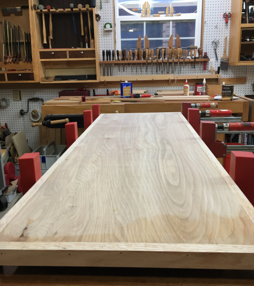 |
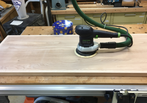
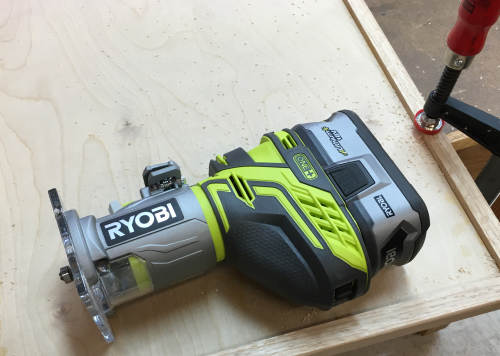
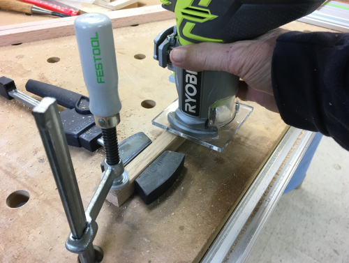
Sanded the slide surface, rounded all edges with a round over bit in a hand held router...machine sanded and hand sanded all edges. |
 |
Milled the lock boards...made the upper lock 1 inch by 1 3/8 inches tall...the lower is one inch by one inch... ...lock boards were glued and screwed (#8 x 1 3/4, #8 x 1 1/2). I made the upper longer since it is really what holds up the ramp...the lower lock board is one inch, the same as the dowel that the lock board will rest on...
|
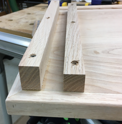 |
I wanted the gap between the two boards to be tight but have some wiggle room...so I installed the smaller lower lock board spaced by a one inch dowel plus a couple of tongue depressor wooden sticks...(~ 3/32) as spacers. |
 |
All surface edges of the sliding
board and the locking boards were routed and hand sanded... |
 |
The slide face of the ramp finished... |
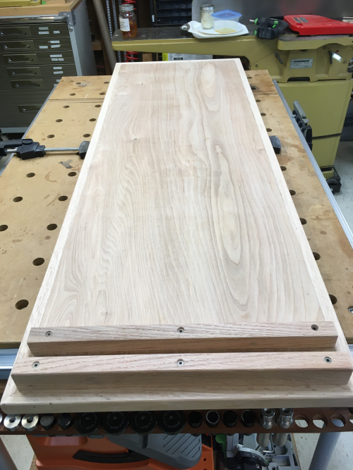 |
Padded on two coats of Super Blond shellac. |
 |
Flipped over to the climb board side...laid out cutoffs to pick out billets...will repead the lock boards on this side plus have climbing handhold strips. |
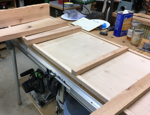 |
Lock boards on this side (which are used when the slide board side is up for play) are the same as the lock boards underneath this side...this climbing slant side has four climbing slats.. ...the bottom slat (at the far end in the image) is 3/4 x 1 1/8, the other slats are 3/4 x 3/4. |
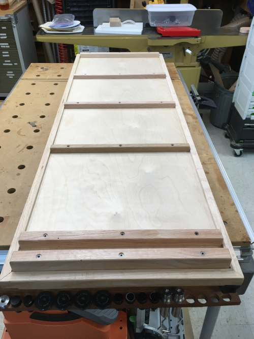 |
All of these slats were given a round over with the router and then were hand sanded to satisfaction. |
 |
The pivot plate as drawn in Sketchup. This drawing was to develop the concept...but when it came to creating the plate it was going to take hands. |
|
A blank of oak plywood was put in place along the outside face of the long frame leg...clamped. |
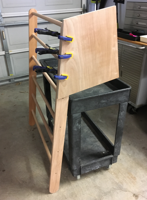 |
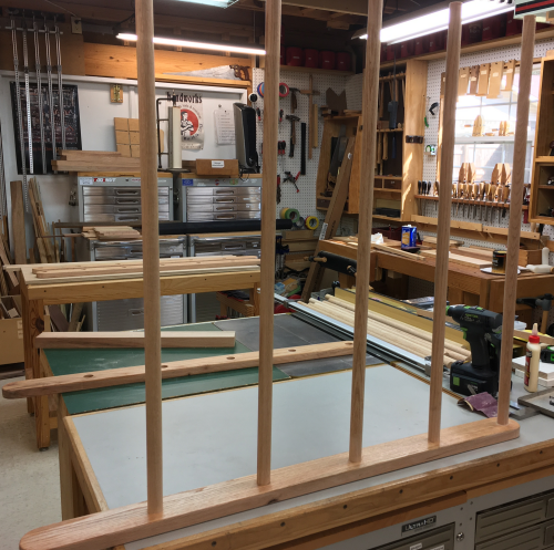
Then the shorter leg frame was moved into a angled position that felt right and clamped. |
 |
The leg frames were moved around until the vision was acceptable, the dowel rods were level...the physical width at the base was moved around until it felt stable... James dropped by this day to work on the chair...he provided the second set of hands and the second set of eyes that really helped me get this done, spatially correct, in a 3d world... |
 |
After the geometry felt right...we scribed off the lines onto the backside of the plate. |
 |
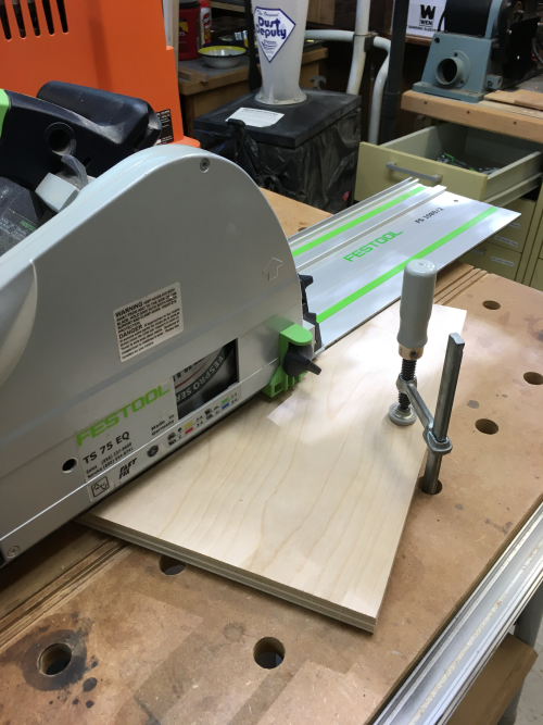
Cut the plate...and then cut
a second plate...the angle cuts were all made much easier with the track
saw. |
 |
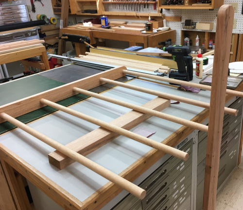
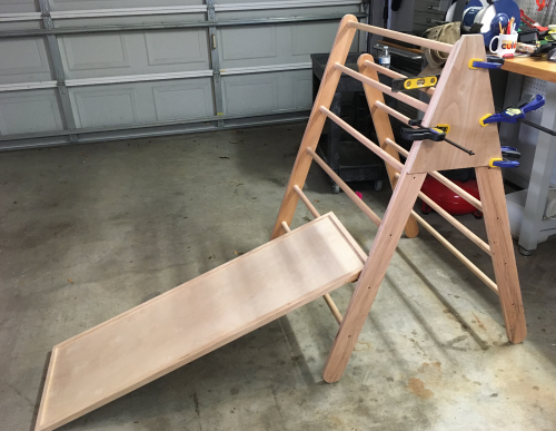
While testing out the pivot plate, I took the opportunity to try out the ramp...all went well.
|
 |
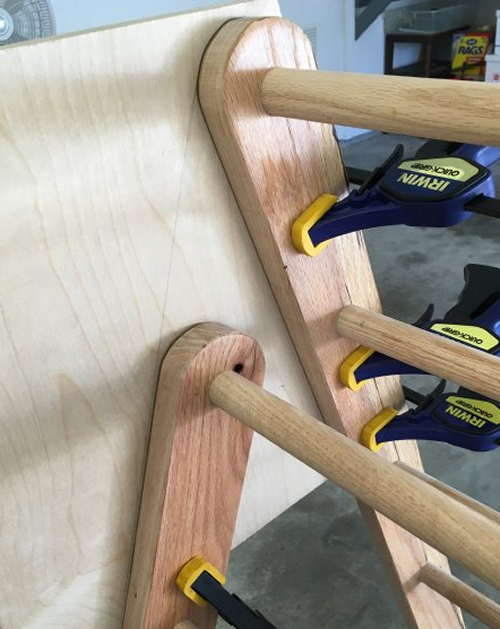
Last test fit...all went well, ready to mark off holes for hardware. These were placed to accomodate the rod dowel insertions. |
 |
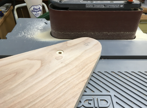
The top edges were rounded at sander... |
 |
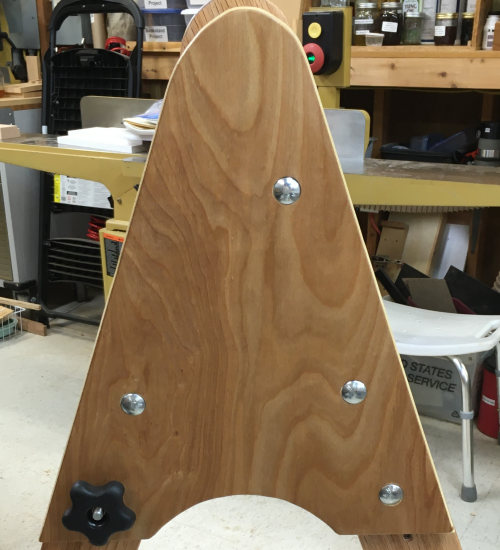
Holes were placed where I felt they were appropriate...all were 1 1/2 inches off of the edges...here are the plates after countersink holes for the four carriage bolts and the through holes for all bolts were placed... |
 |
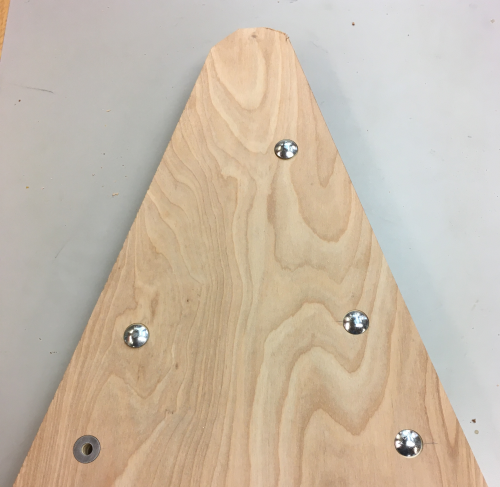
All of these holes were drilled at the drill press...here is a test fit for all hardware... |
 |
All of the corresponding holes in the frames had to be done with handheld drills...accuracy was an issue...it was hard to stay perpendicular. The only real error I made during this entire build was the first hole that I drilled. I clamped the frame to the bench...and walked around to another angle to have a better grip on the drill...flip flopped my brain in space and drilled the lower hole (handle hole) like the upper hole. |
 |
Blowouts and hole fit adjustments were made with sandpaper and rifflers... |
 |
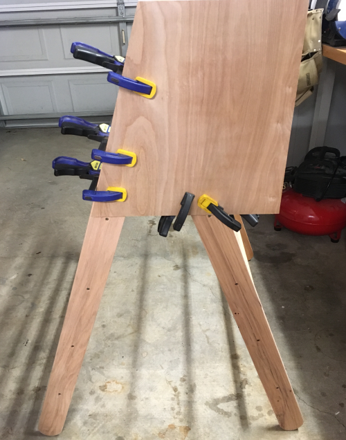
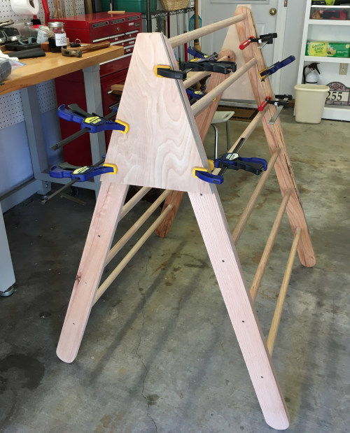
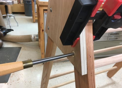
Lining up the holes, holding the two frames in space, was difficult...here the first plate is in position. |
 |
Lining up the holes on the second plate was driving me crazy until I got out the Lie-Nielsen drawbore pins...alignment was much easier with the pins...wish I had used them all along... |
 |
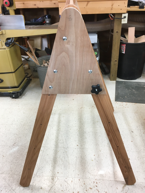
Both plates in...the Pikler is complete...need some edges rounded, etc... |
 |
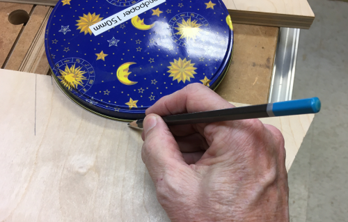
I wanted to break the lines of the lower edge of the pivot plates. Traced out a suitable curve... |
 |
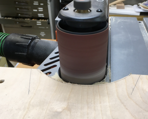
Cut out the arc with a jig saw...cut it fat... |
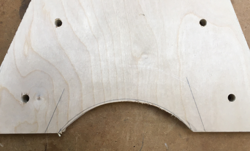 |
Then sanded to the line. |
 |
...and some shellac. |
 |
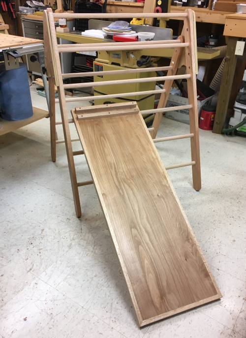
The final assembly ...the Pikler. |
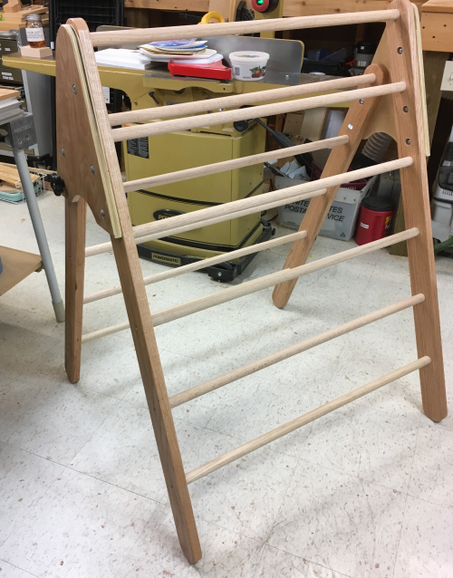 |
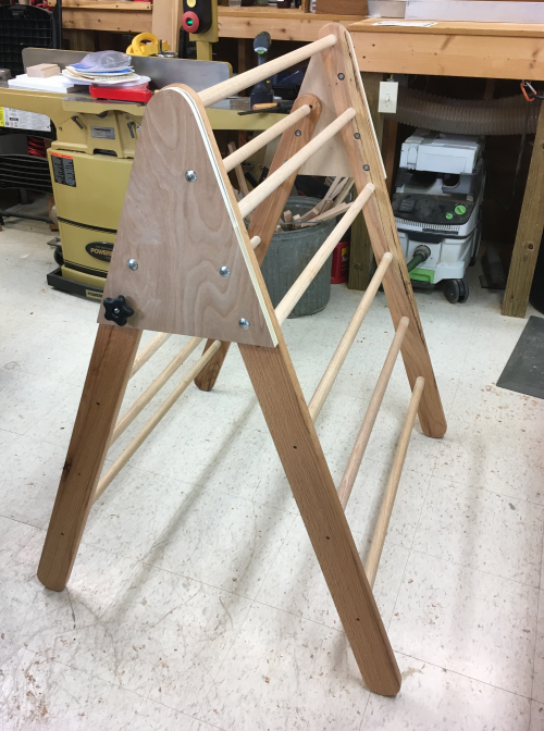
The Pikler with the climbing ramp... |
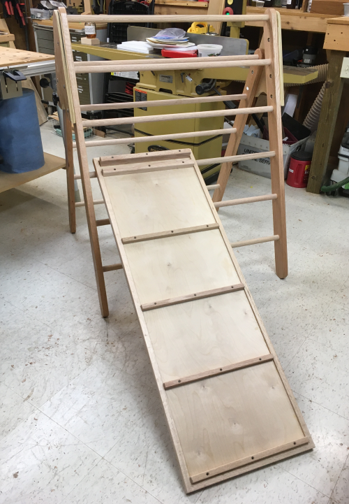 |
The Pikler with the sliding ramp... |
 |
Folding the unit...after removing the handles, the short frame will pivot on the single carriage pivot bolt...this brings the short frame in closer. |
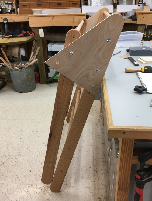 |
The handles are T-bolts...there is a plate that fits into a recessed area in the wood on the inside of the legs. |
 |
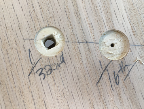
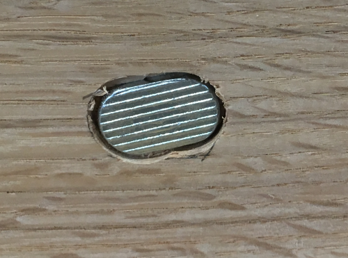
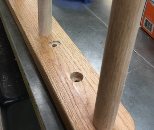
Here is the comparison...a round, deep hole for the carriage bolt washer and nut vs the shallow oblong hole for the T-bolt plate. |
 |
Here is the bolt plate in the shallow hole. |
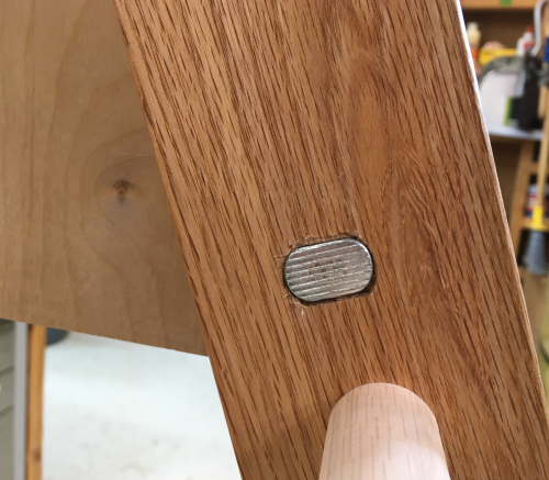 |
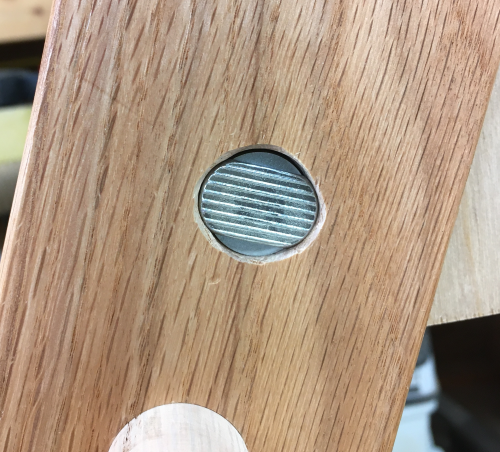
Here is the bolt plate in the "oops, I messed up" deeper hole. I oblated the hole with a carving gouge and then put in washers to compensate for the depth. |
 |
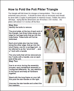
Instructions for disassembling
the Pikler, folding it, and reassembling it are available here...PDF. |
 |
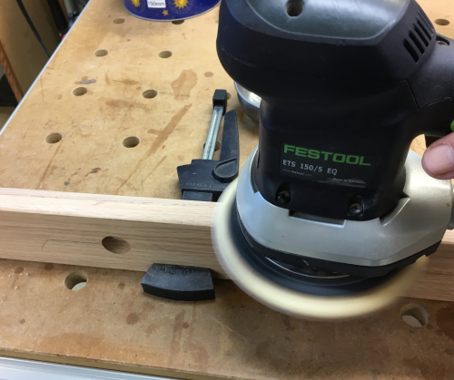
After miling, the leg blanks were sanded on edge and face at 120x and 220x...Rotex 150mm. |
 |
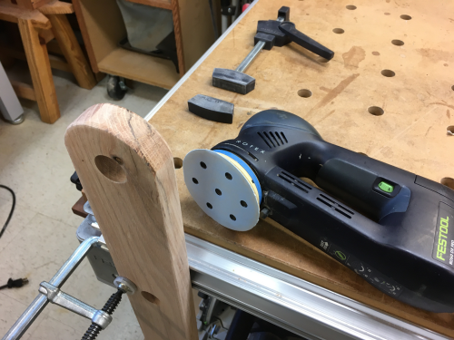
End grain was worked 220x with 90mm if needed... |
 |
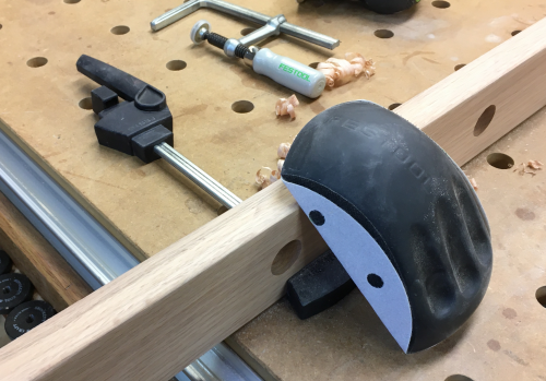
...most edges were finished with 220x hand sanding. |
 |
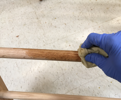
I did not want to have to rub
on shellac around the dowel rods...so I rubbed on my #2 Super Blonde
shellac mix prior to putting in the rods. |
|
Each rod was lightly hand sanded (100x) on the ends prior
to assembly. |
 |